
![]()
Remove the 20mm spacers
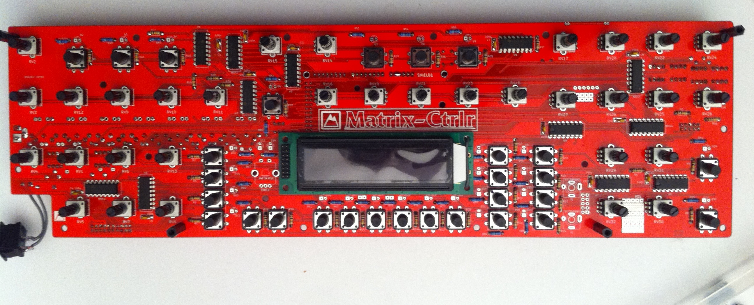
Step 16 : LCD (critical step)
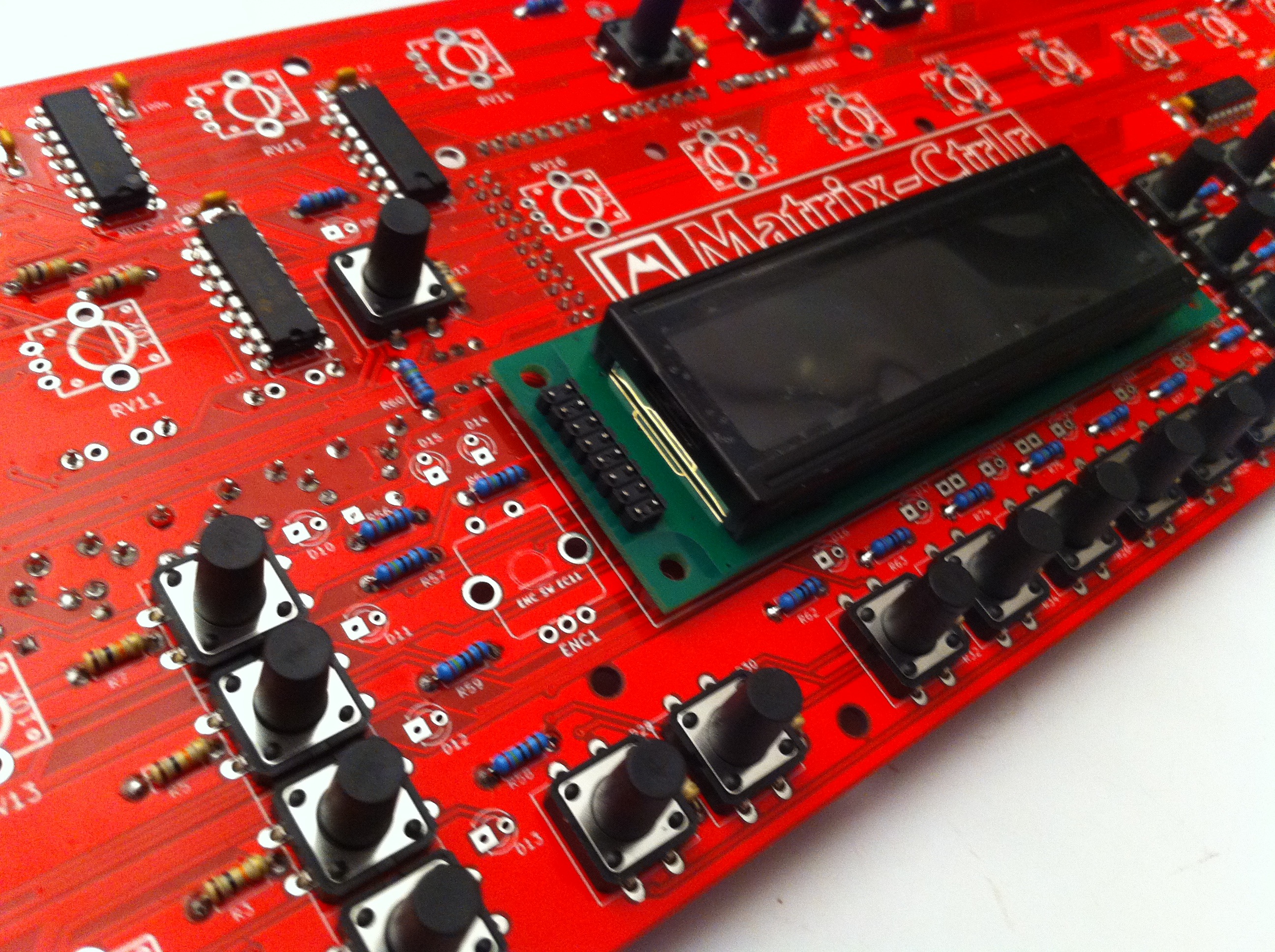
Insert the LCD into its footprint on the top of the PCB. Do not solder it yet!
PCB prior rev1.4 :
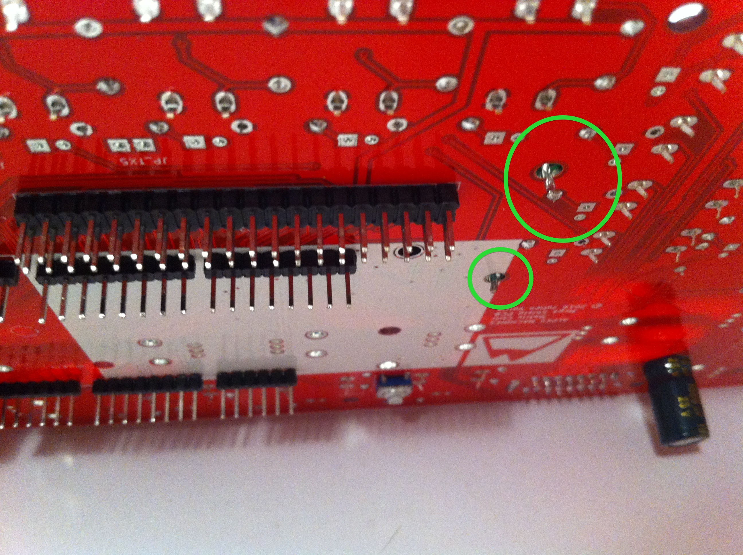
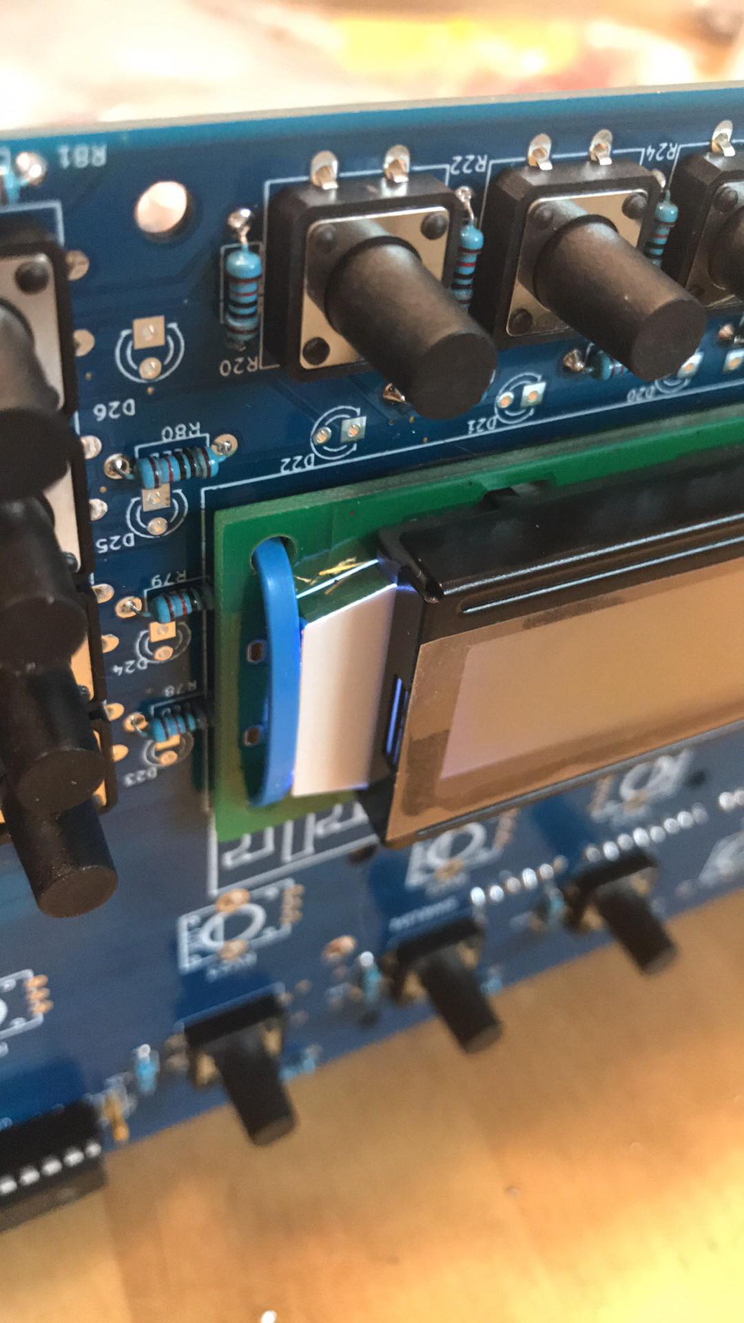
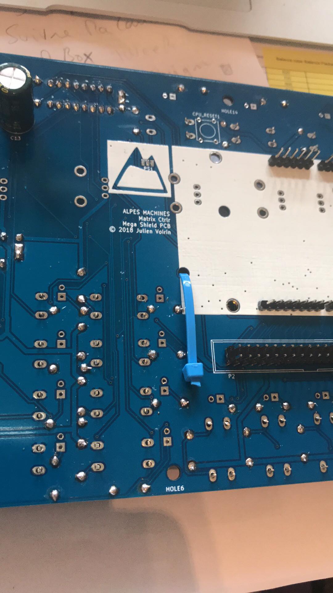
Cut a piece of wire. You will use it to attach the LCD board to the PCB using solder on the back side of the PCB in the M3 Mainboard holes.
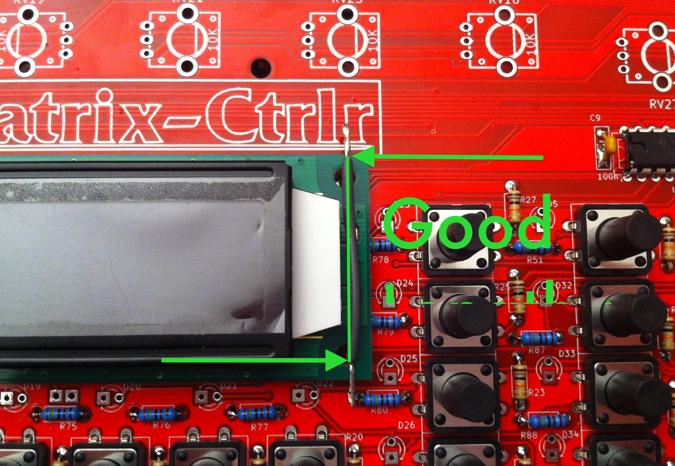


PCB rev1.4 : if the holes are not metallised , you will use a plastic strap to attach the LCD to the TOP face of the PCB. this depends of the factory batch : check your received components bag.

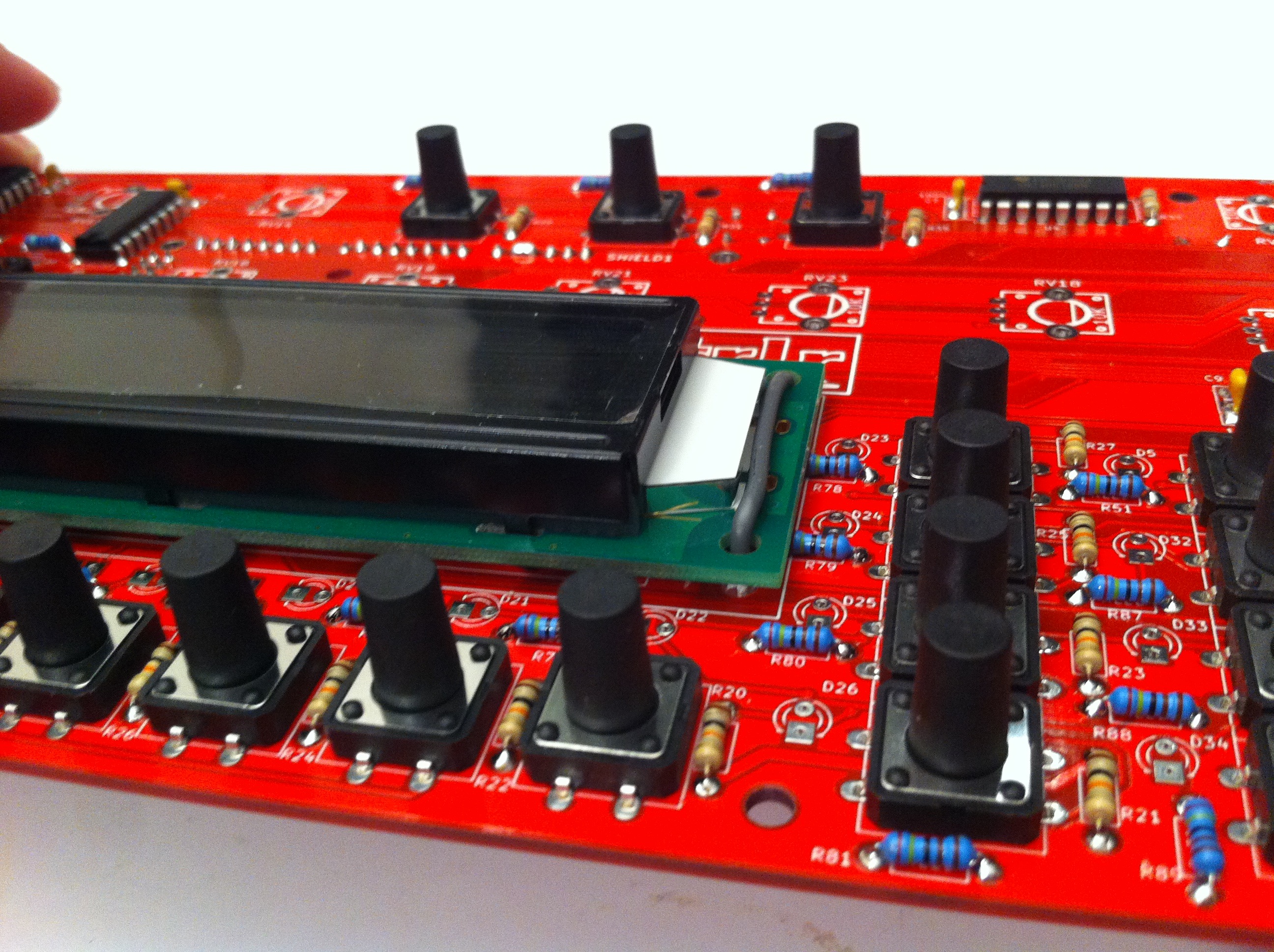
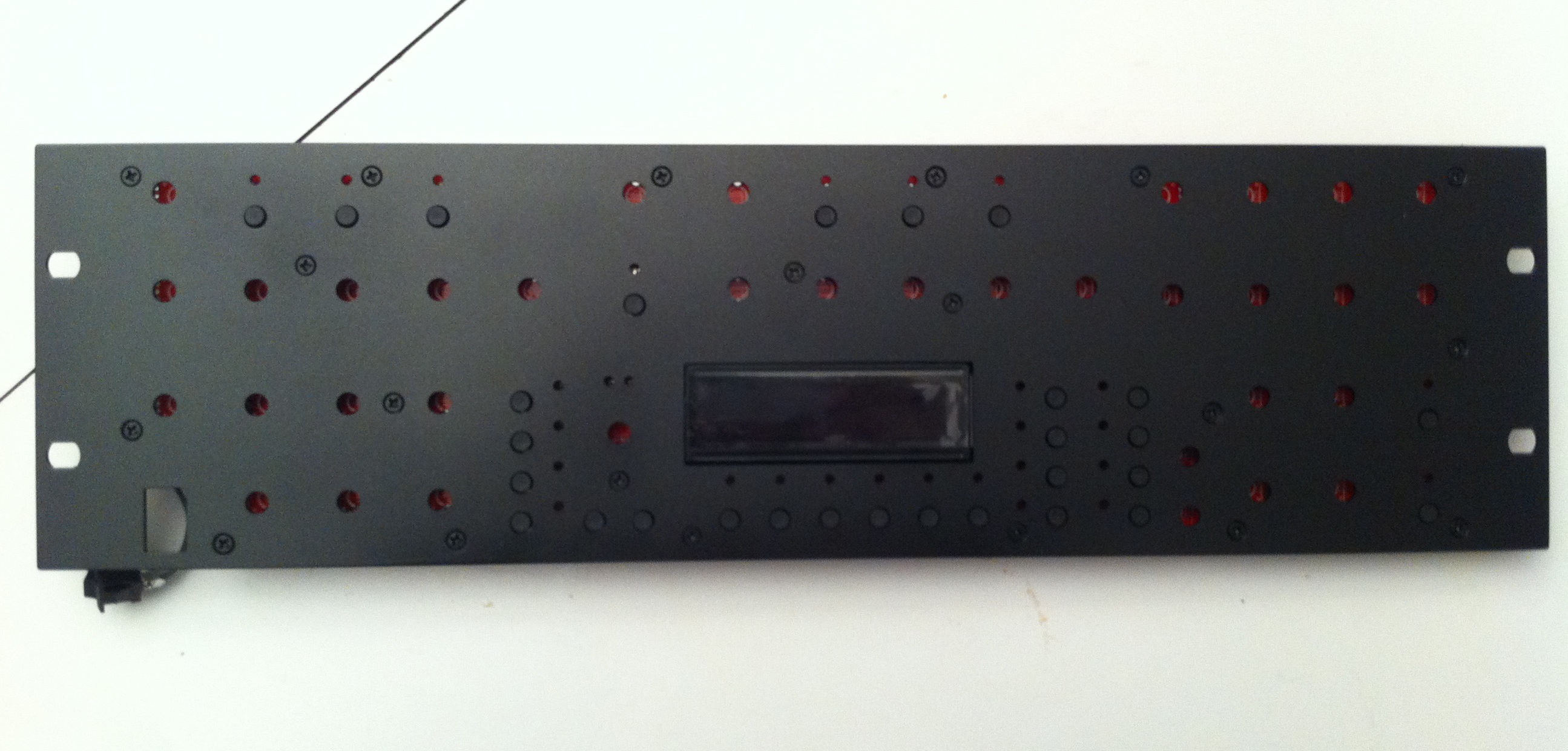
Take the front panel and assemble the sandwich using screws. Notice the LCD is loose, so take care. Align the LCD perfectly in the frame, so that you can’t see it over the panel when you look from the sides. Tighten M3 black spacers & screws.

The LCD is held between the front panel surface and the PCB. Use the switches to perfectly align the PCB and front panel. Take your time. Make necessary adjustments, screw/unscrew until it’s perfectly aligned. This is a very important stage and you won’t be able to go back if it isn’t done right.

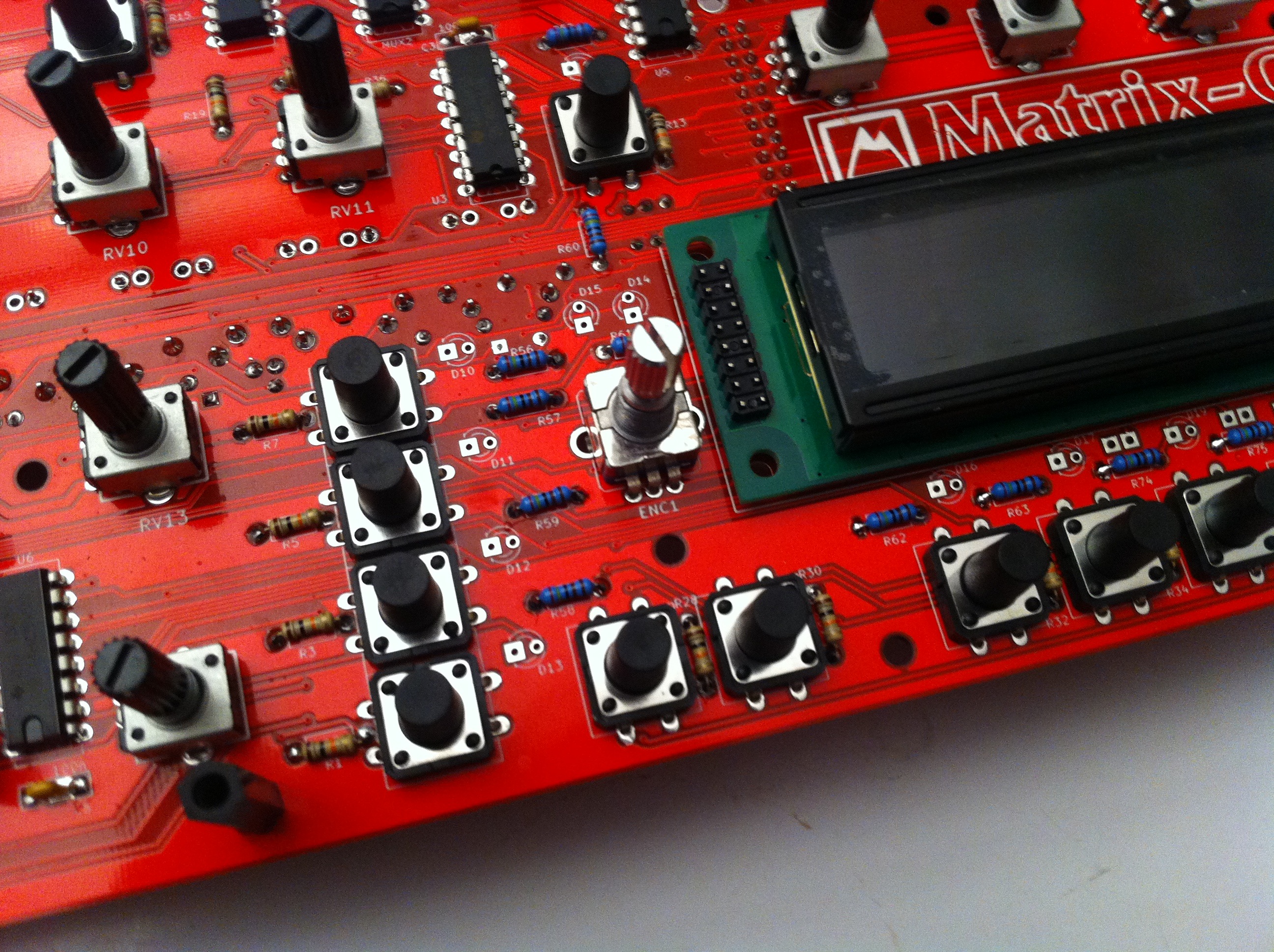
When you’re confident in your work, solder ONE pin of the LCD connector to the bottom side of the PCB.
Again, check the alignment. If it is good, solder another pin. Check again, and so on until the last pin is complete. Once all pins are soldered you can setup contrast, not before.
Don’t use too much solder in a first time as desoldering may be very complicated.
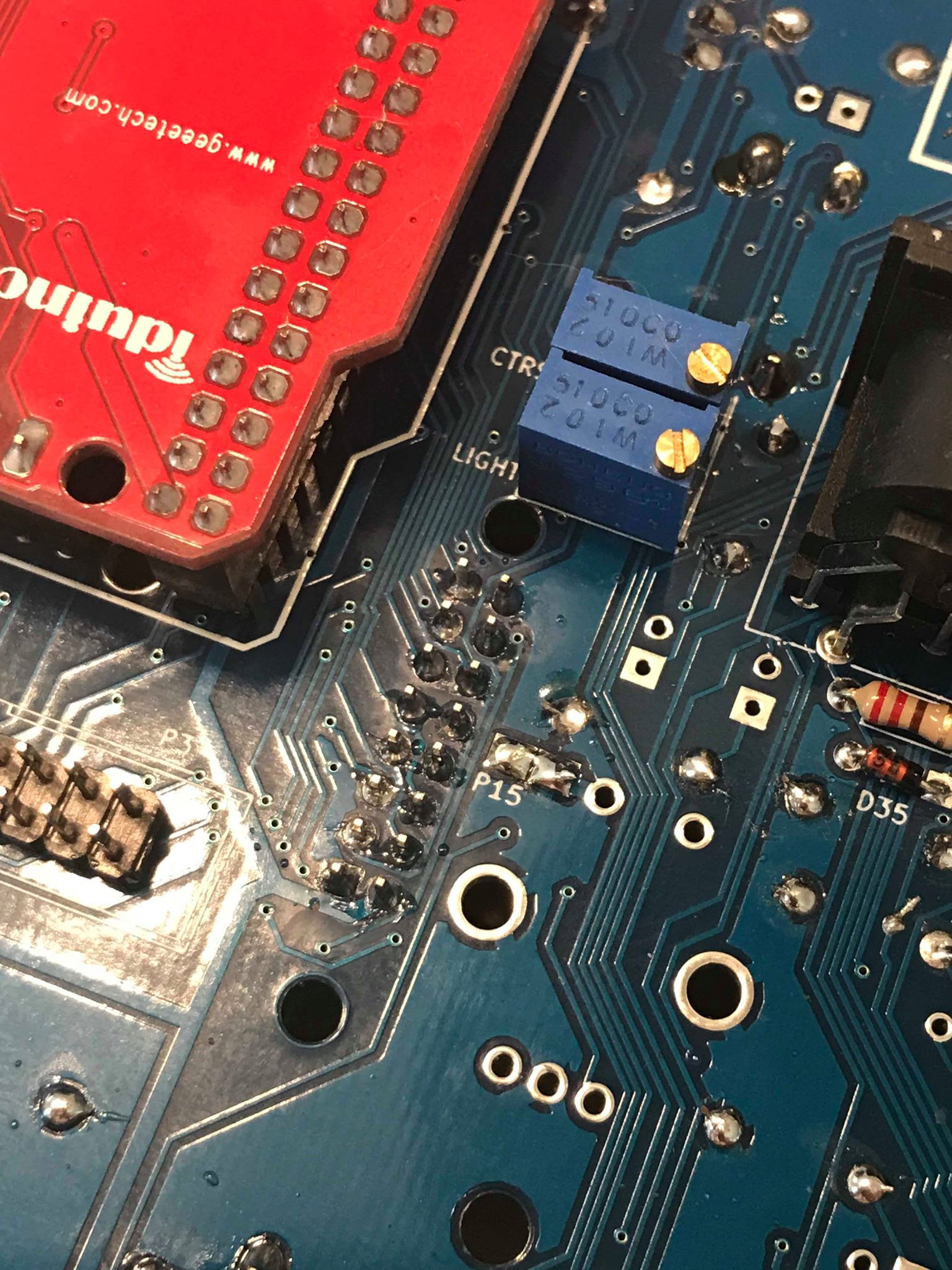
Put a solder blob on the P15 connector to connect the pin 5 of the LCD (R/W) to the ground (you could also use a jumper). check schematic if necessary.
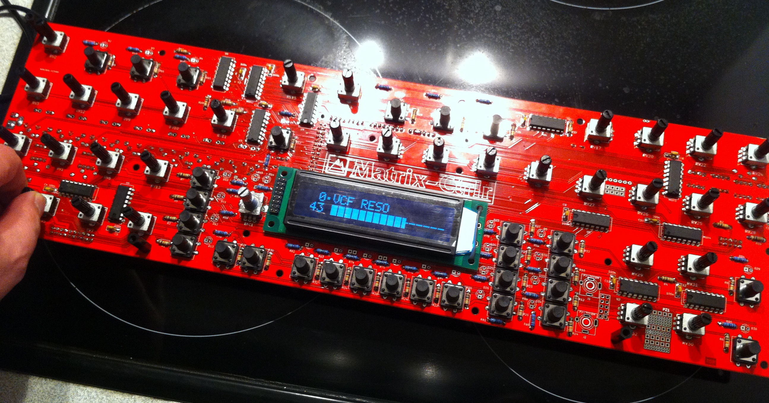
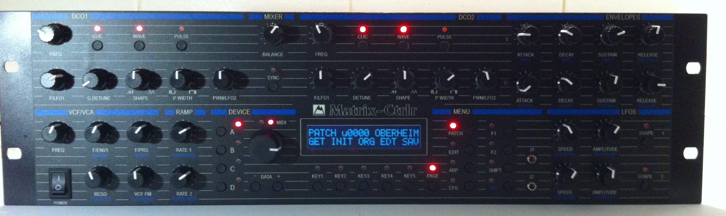
Setup the display (light + contrast) : First turn LIGHT1 clockwise to softly highlight the LCD. Then turn CTRST1 counterclockwise to set up the contrast of the LCD : characters should appear on the display. If nothing appears, turn clockwise.
If you don’t, this would fail the display initialization resulting in solid blocks like below :
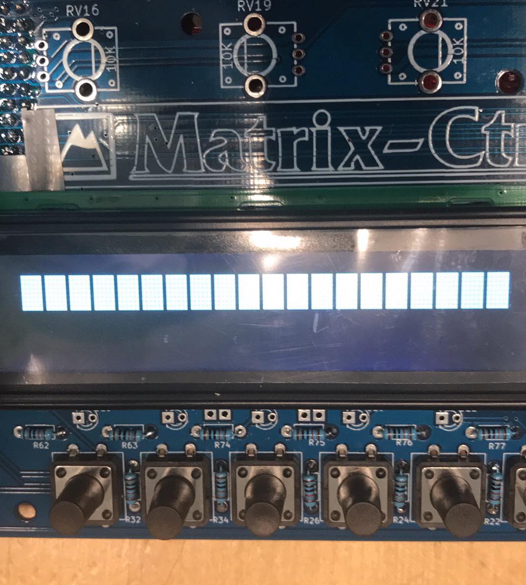
Set up Contrast and Light : turn LIGHT1 clockwise until you see the backlight illuminating. Then turn CTRST1 counterclockwise until you see characters on the display. It will display random information: that’s normal, you haven’t yet soldered in the potentiometers and the arduino’s ADC generates random values.
Step 17 : Potentiometers, Encoder
RV1,RV2 … RV32
ENC1
Place all of the potentiometers in their footprints, close against the board. Same for the encoder.
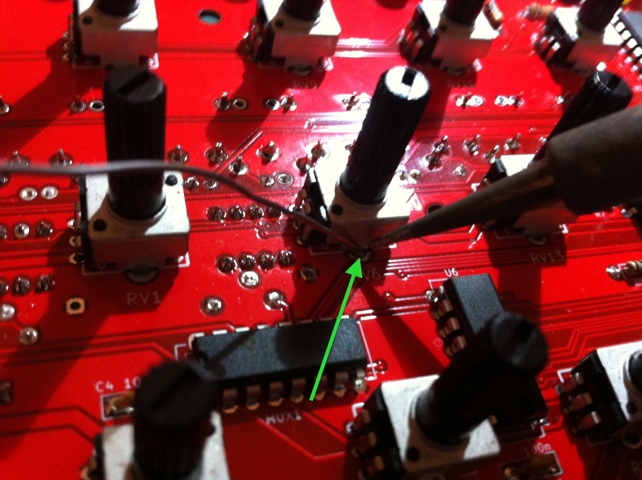
Solder one of their snap-in leads (e.g the bottom lead) to the PCB from the top.
Check the alignment again. Reheat and reseat if necessary.
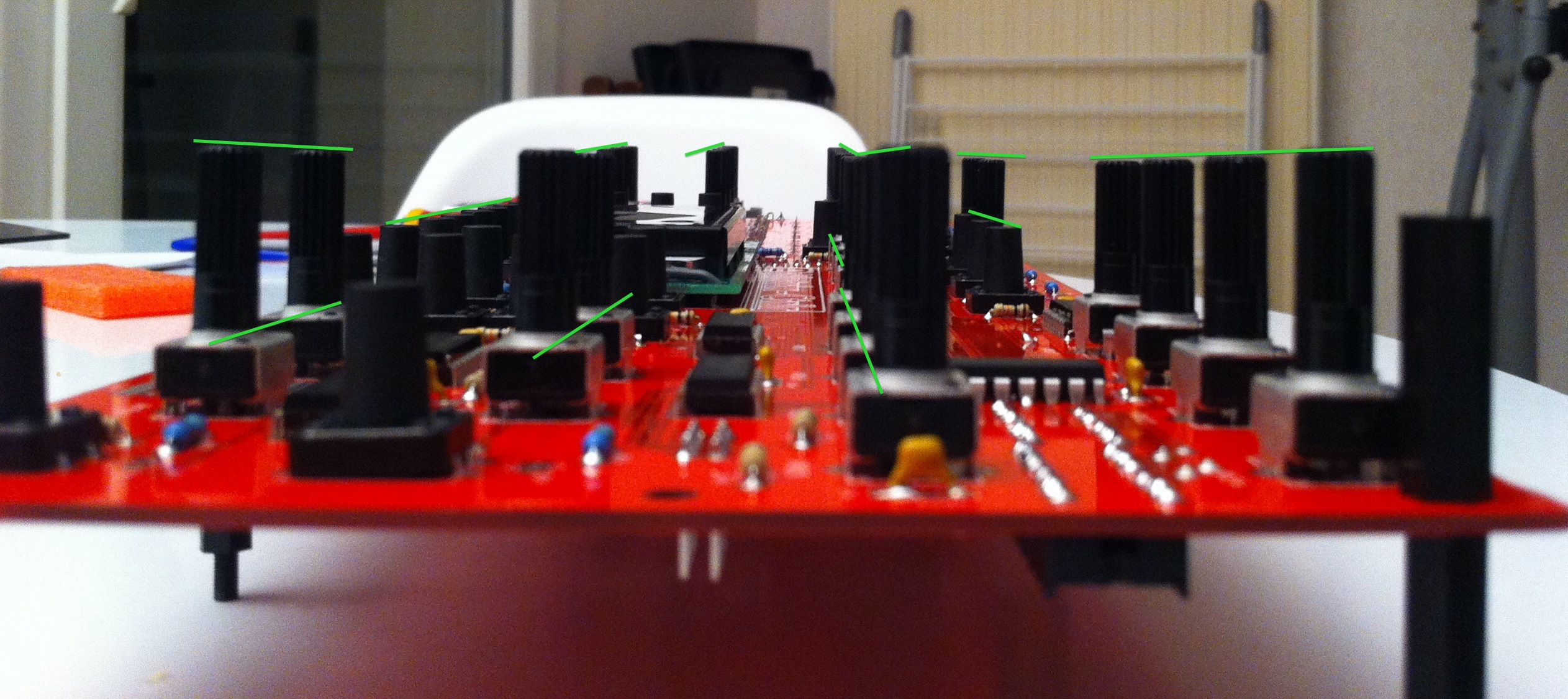

Place and tighten the front panel with screws. Check the alignment again.
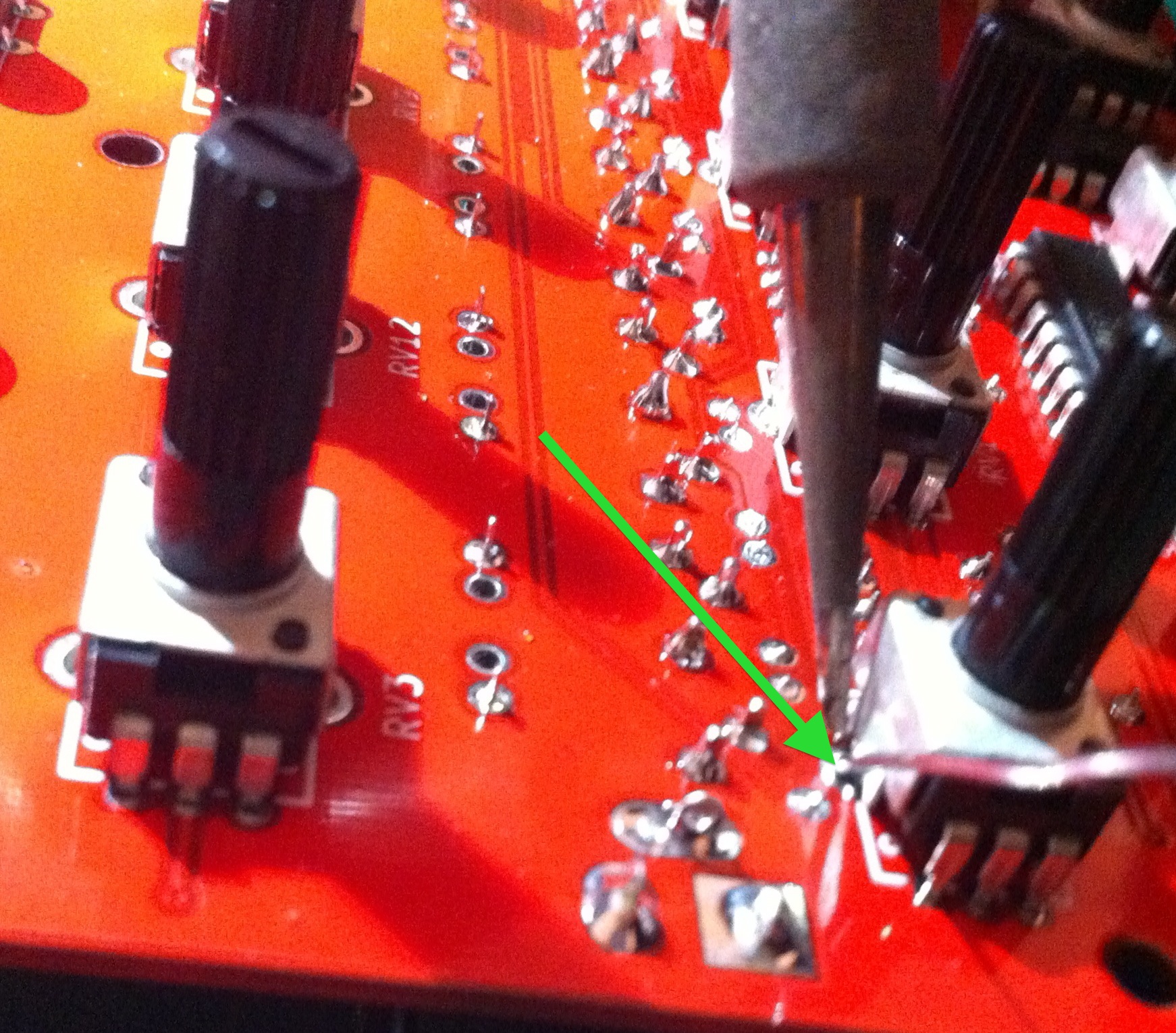
Then flip the PCB over and solder leads 1,2 and 3 of the pots.
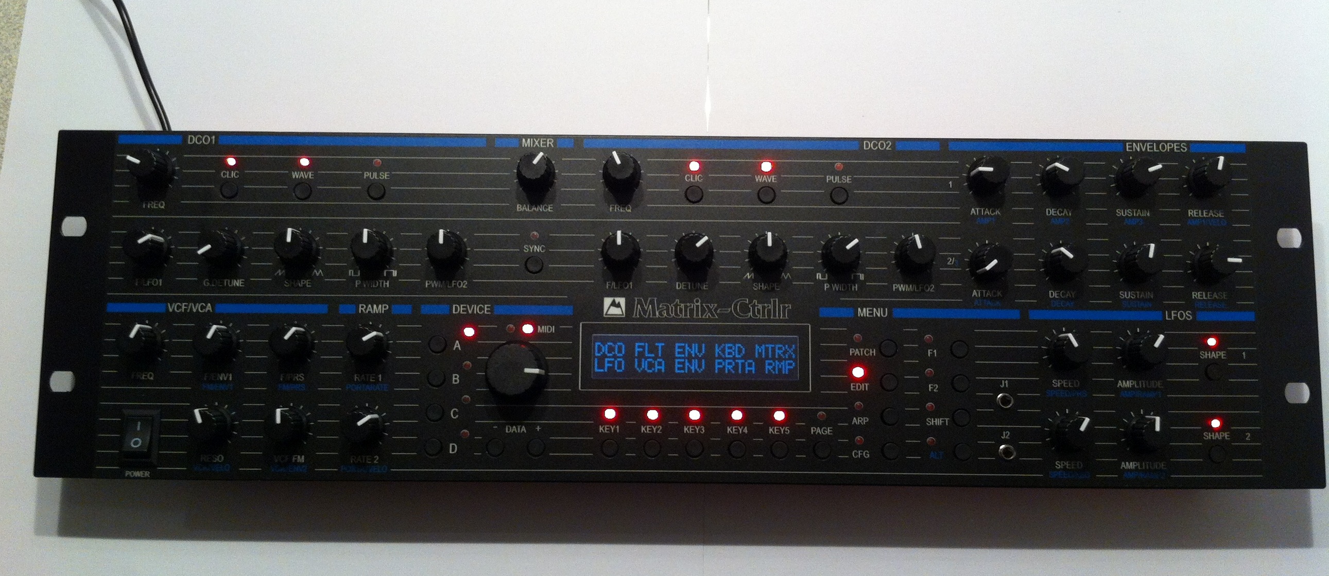
At this point you can check that your Matrix Ctrlr is working. If you turn the pots you will send MIDI data and you can navigate through the menus using the switches: the end is near my friend!
There is a TEST MODE with recent firmware : press F1+F2 on boot to enter the test mode. This way you can check that potentiometers are well soldered : if a value is constantly displayed and flickering, you have probably not soldered the potentiometer. Pressing the switches light up the LED next to them. once again, no reaction = no soldering.
Regarding the encoder : depending of the suppliers, it decrements or increments when you turn counter clock wise. There is the possibility to set normal or inverted behaviour in the CFG menu
Solder the last snap-in leads of the potentiometers while checking the alignment on the front panel. Cut the snap-in leads touching the arduino power connector.
Encoder behavior is configurable in CFG Menu (see later).
Step 18 : Jacks 1/8″
J1 J2
Remove M3 screws and slowly, gently remove front panel. The LCD should stay in place.
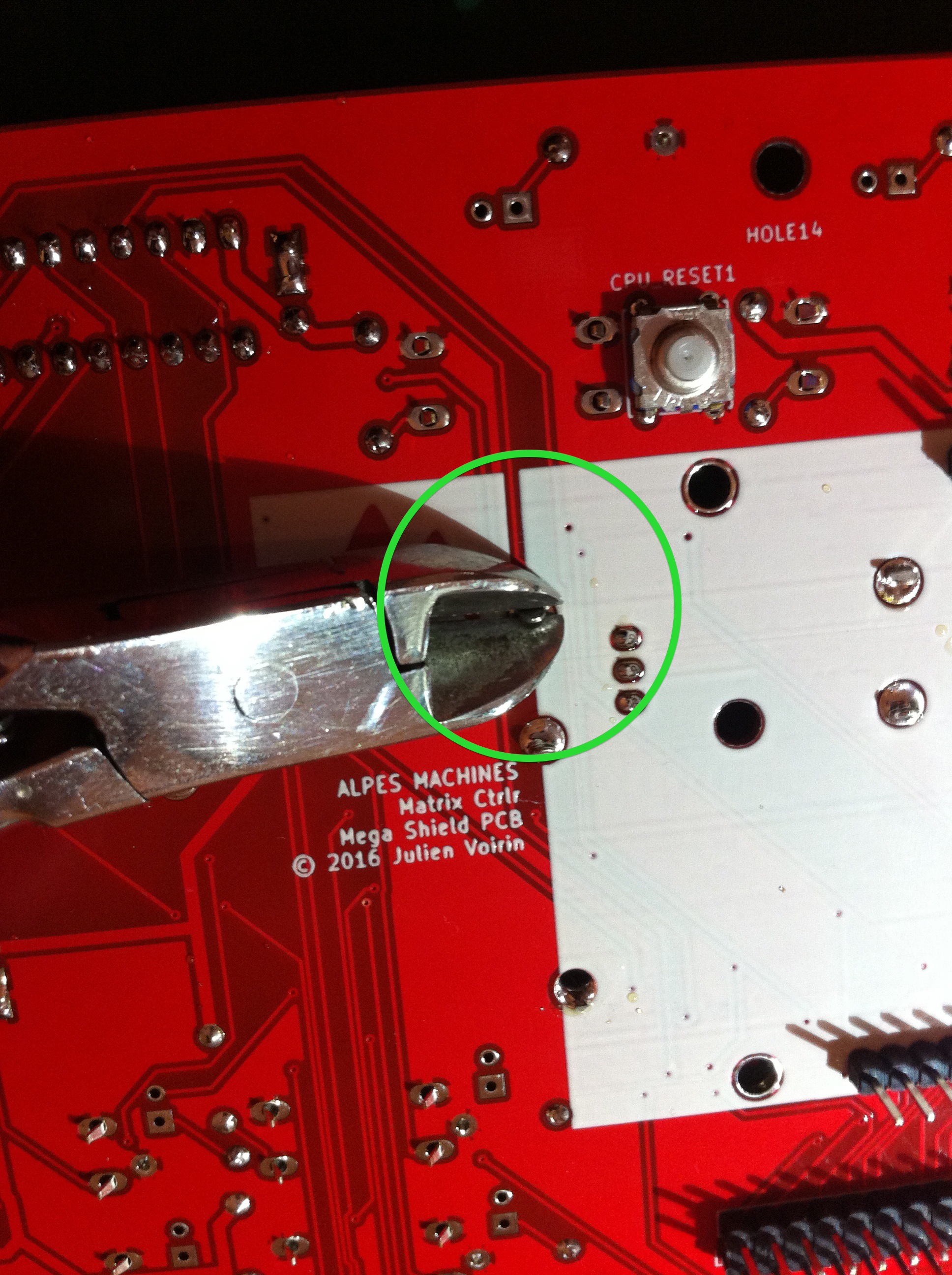
You will now adapt jacks for the PCB by creating a ground using the cut leads from the beginning of the build.
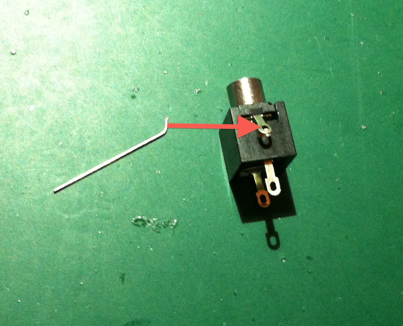
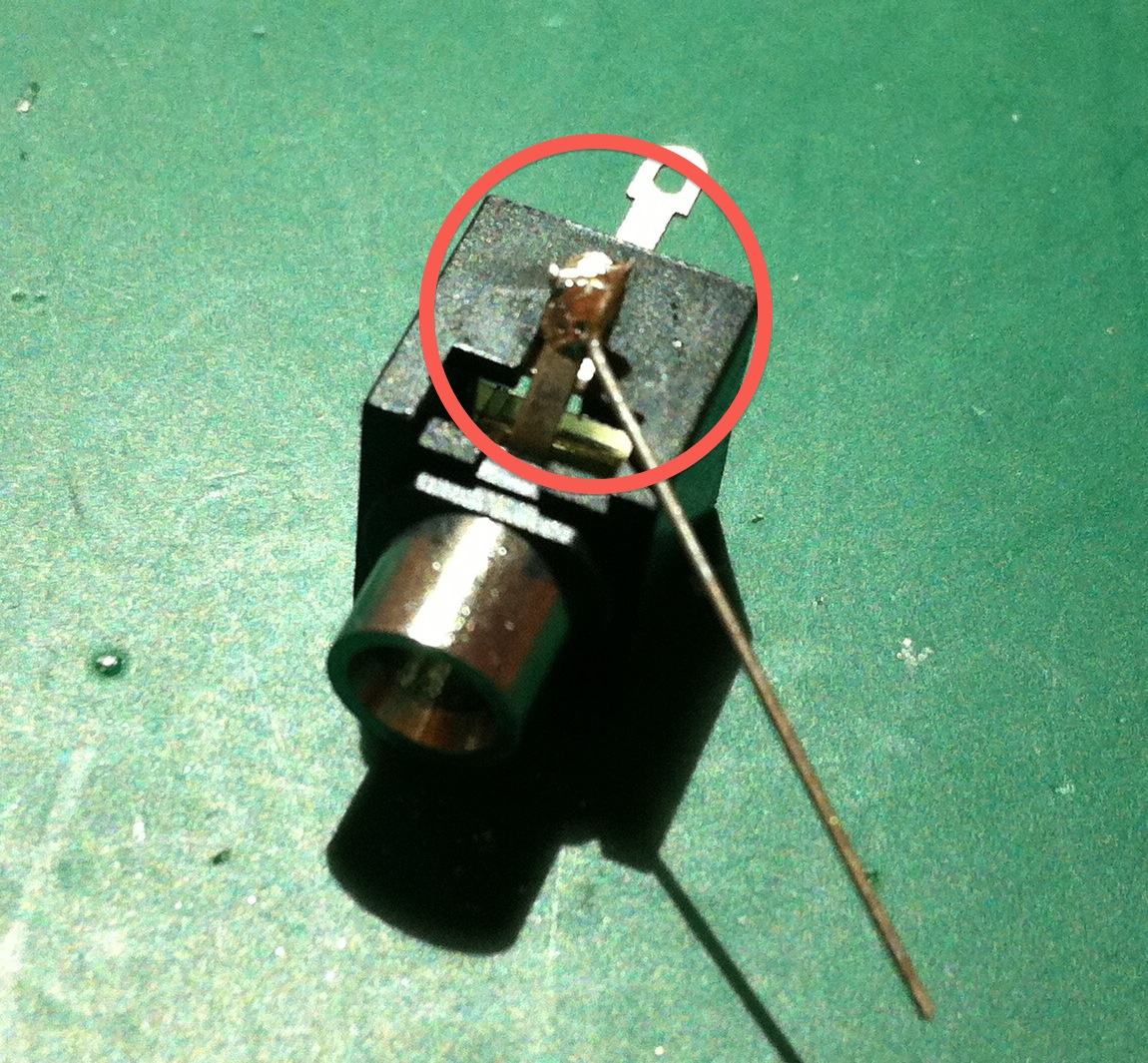
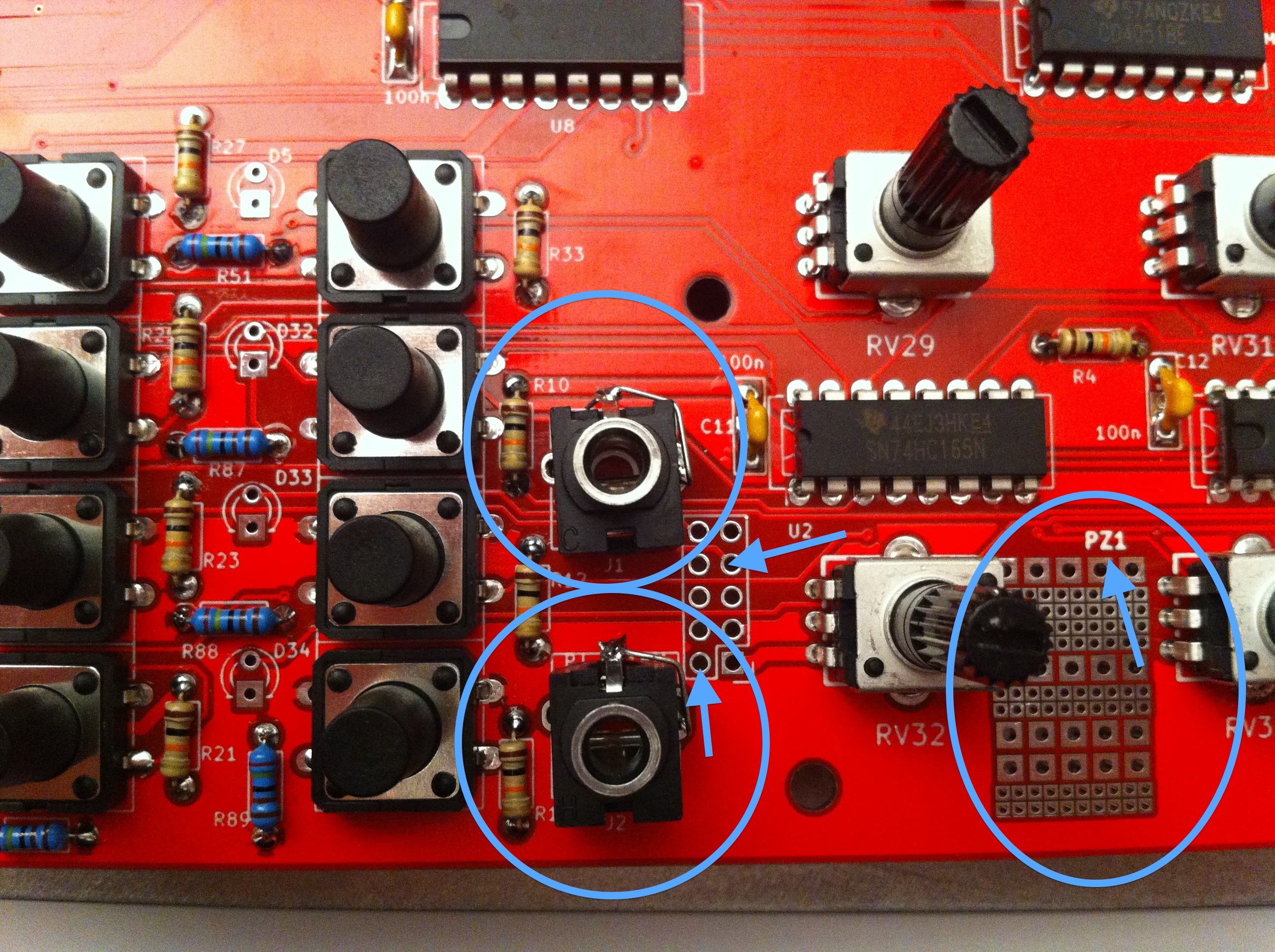
Snap the jacks into their footprint. Observe their orientation.
Using pliers and a cut lead (those from a resistor, for example), create the ground lead of the jack as in the picture below. The footprint has ground on both sides, it’s easier in the round pad.
RQ : PJ-301BM fits perfectly into the footprint, but is hard to get. Its height is not good.

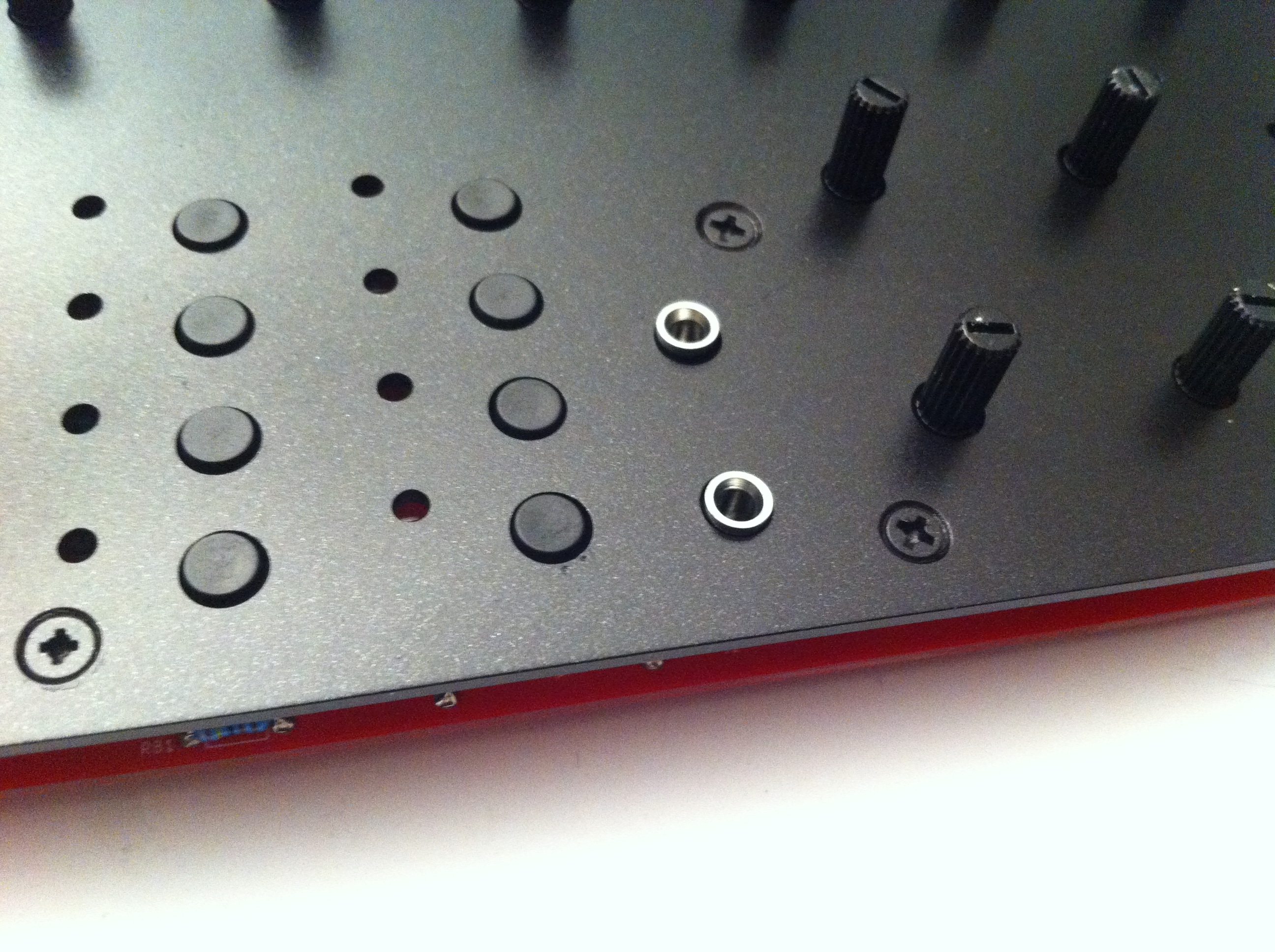
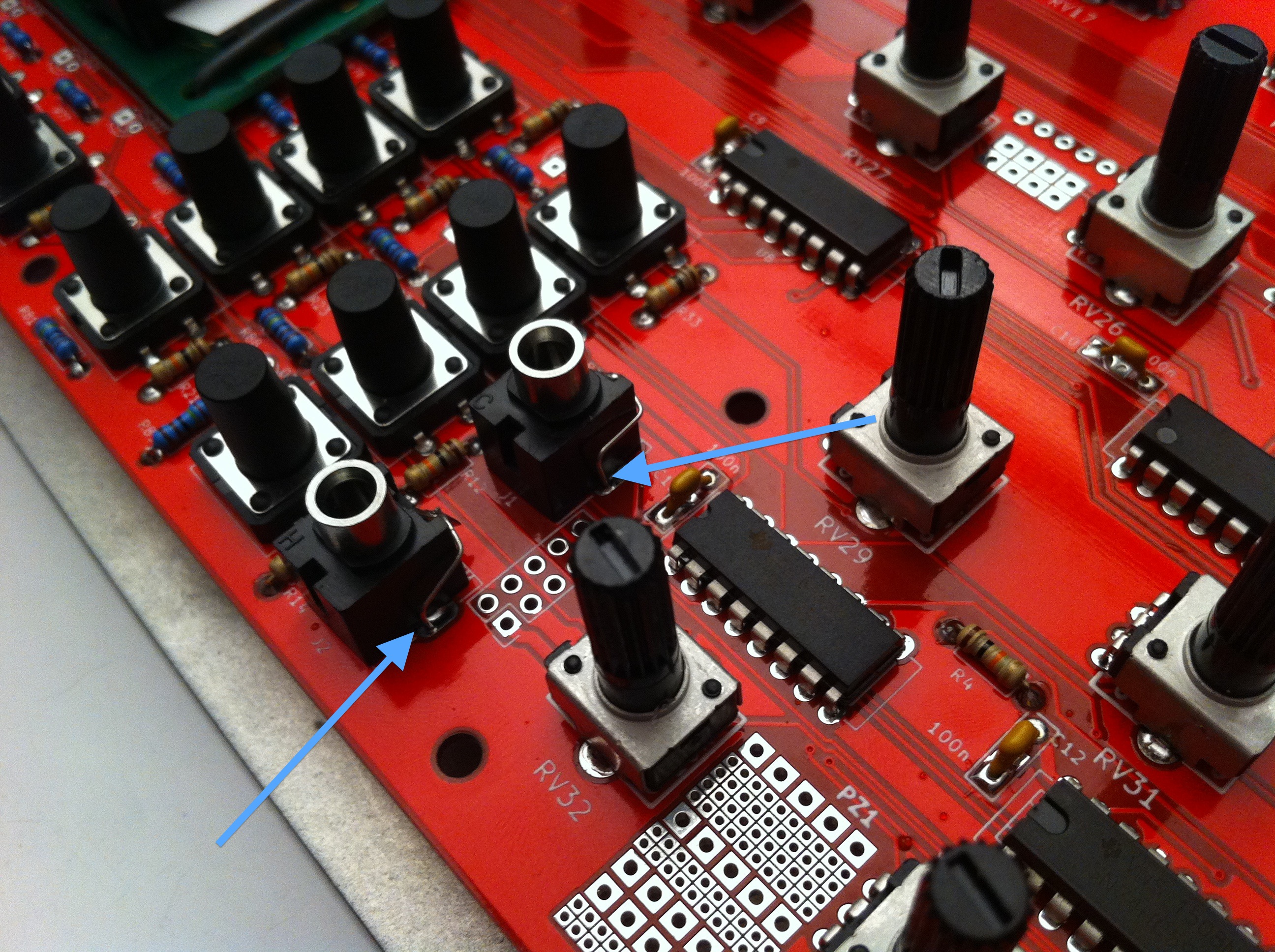
Replace front panel, align and then solder the jacks while holding them to the PCB. Take your time doing this.

RQ : PZ1 is a prototyping zone next to the jacks so that you can create your own circuitry to interface the jacks to the arduino’s free pins P2 and P3 using Dupont cables.
NOTA : since PCB rev1.4 (blue), CV1 and CV2 are used to directly connect the Jacks J1 & J2 to the arduino through 8 jumpers. Use 2X4 DIL headers and configure jumpers like images below :
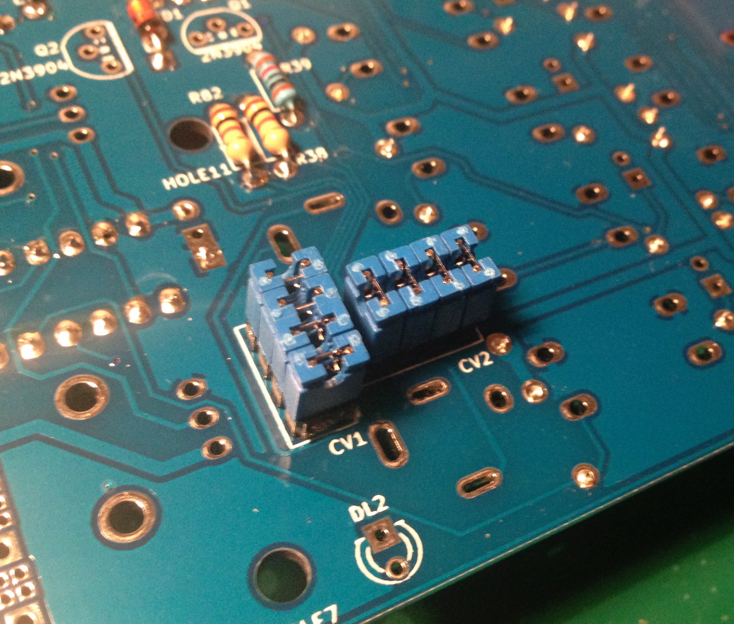
You will need to complete area near CV1 CV2 connectors with 2N3904 transistors, 1K & 10K resistors and 5.1V Zener Diodes ZD1 & ZD2 : this protects the arduino and limits the input voltage to +5V.
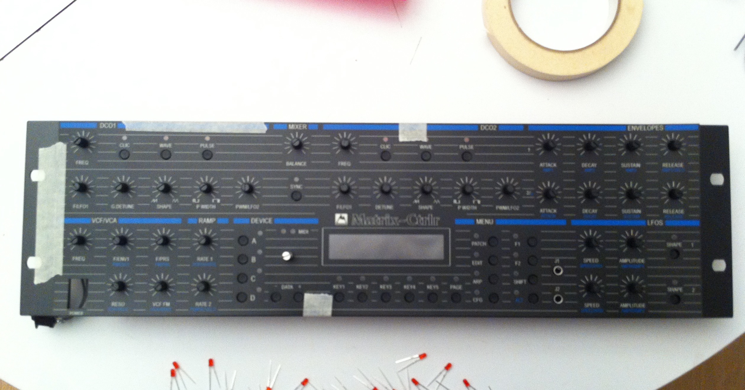
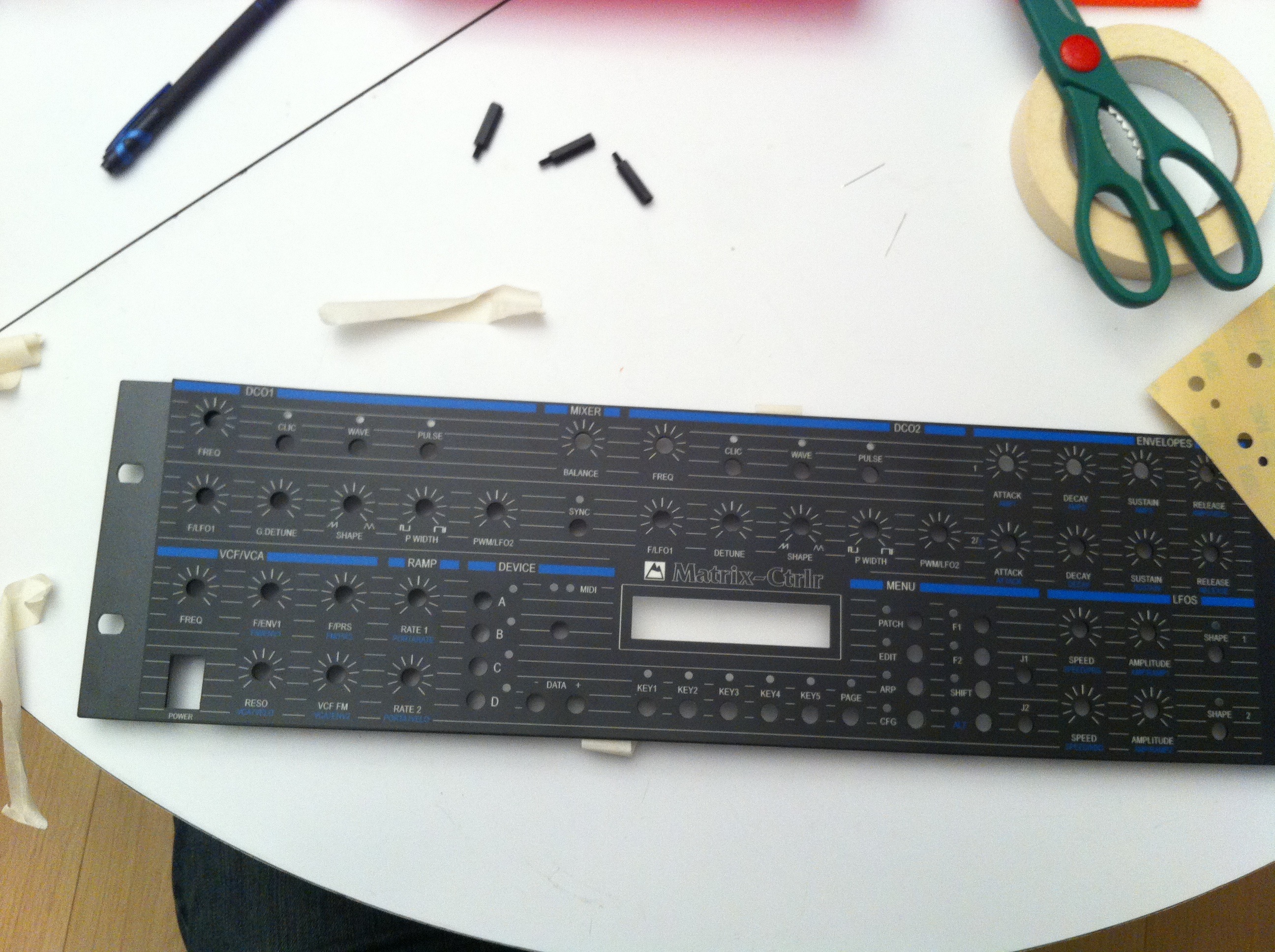
Step 19 : Lexan (critical)
Lexan v200 UV
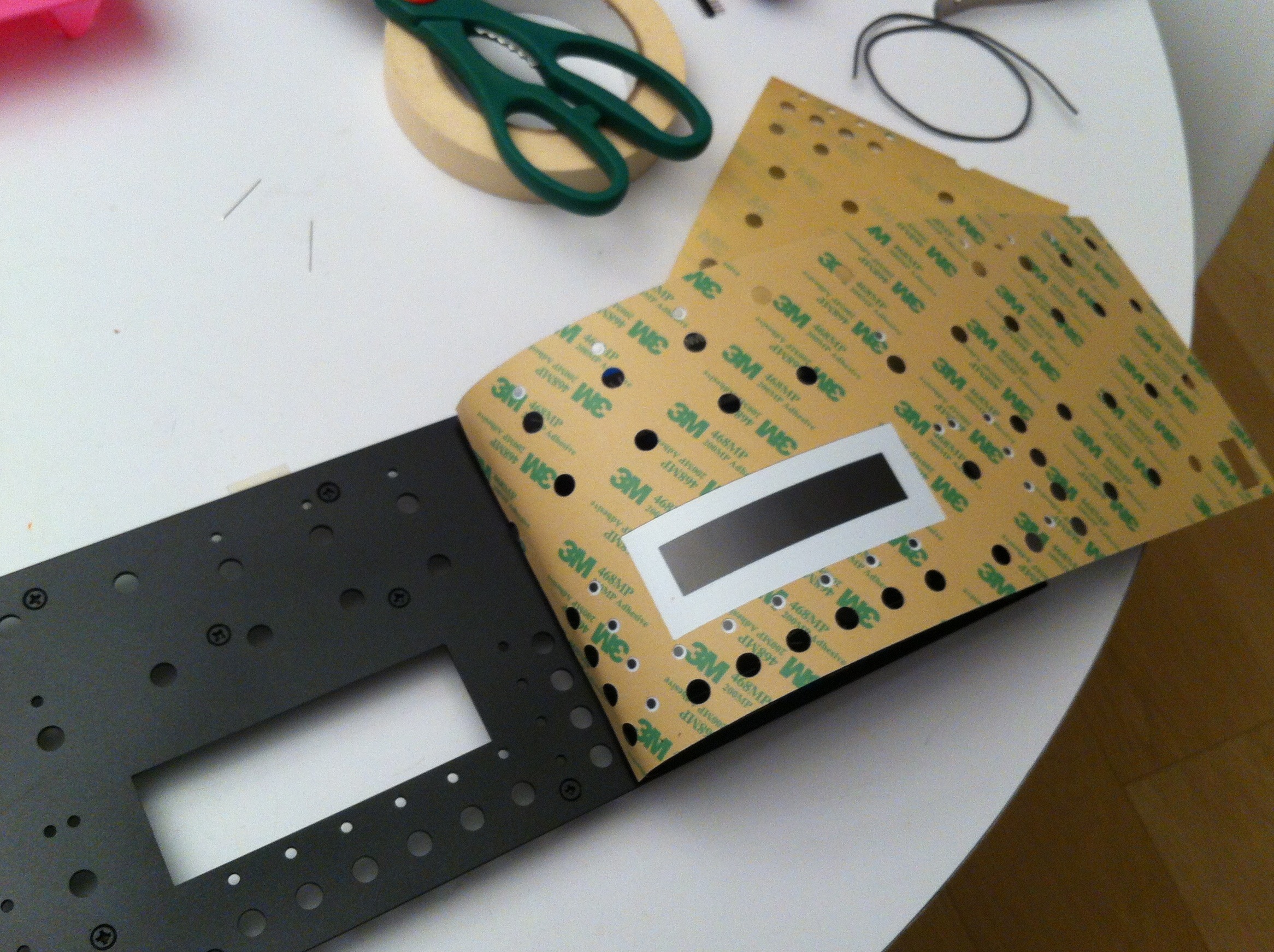
Place the overlay on the front panel, center, adjust and use tape to hold it in place. Leave one edge free.
Peel the backing of the adhesive and cut.
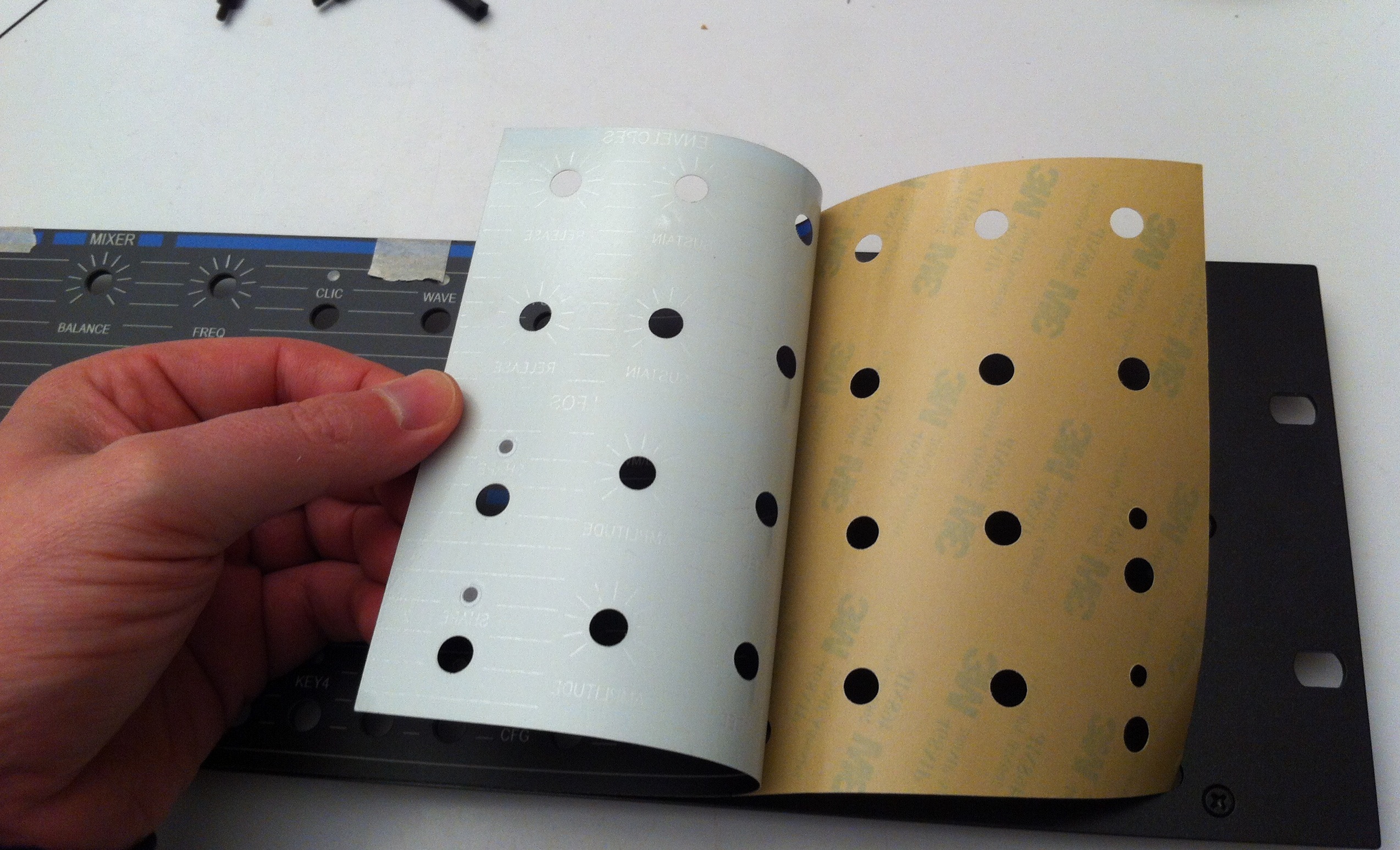

Adhere one edge of the overlay to the front panel and while removing rest of the adhesive roll the overlay down across the front panel.
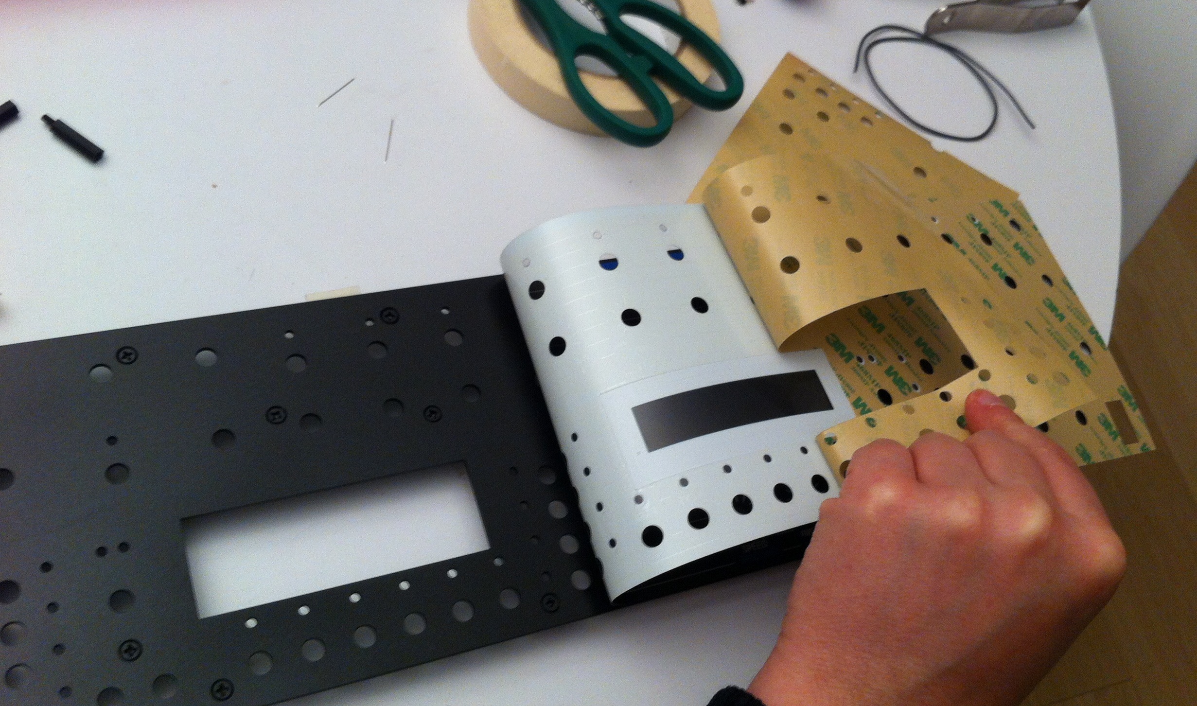
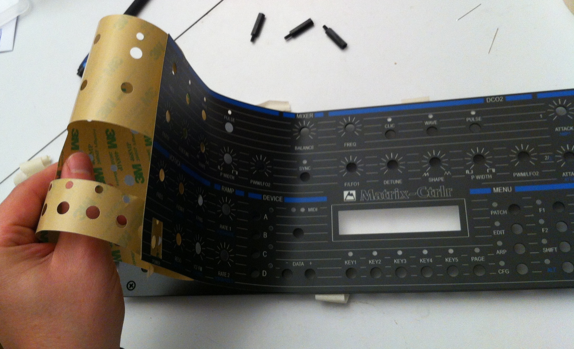
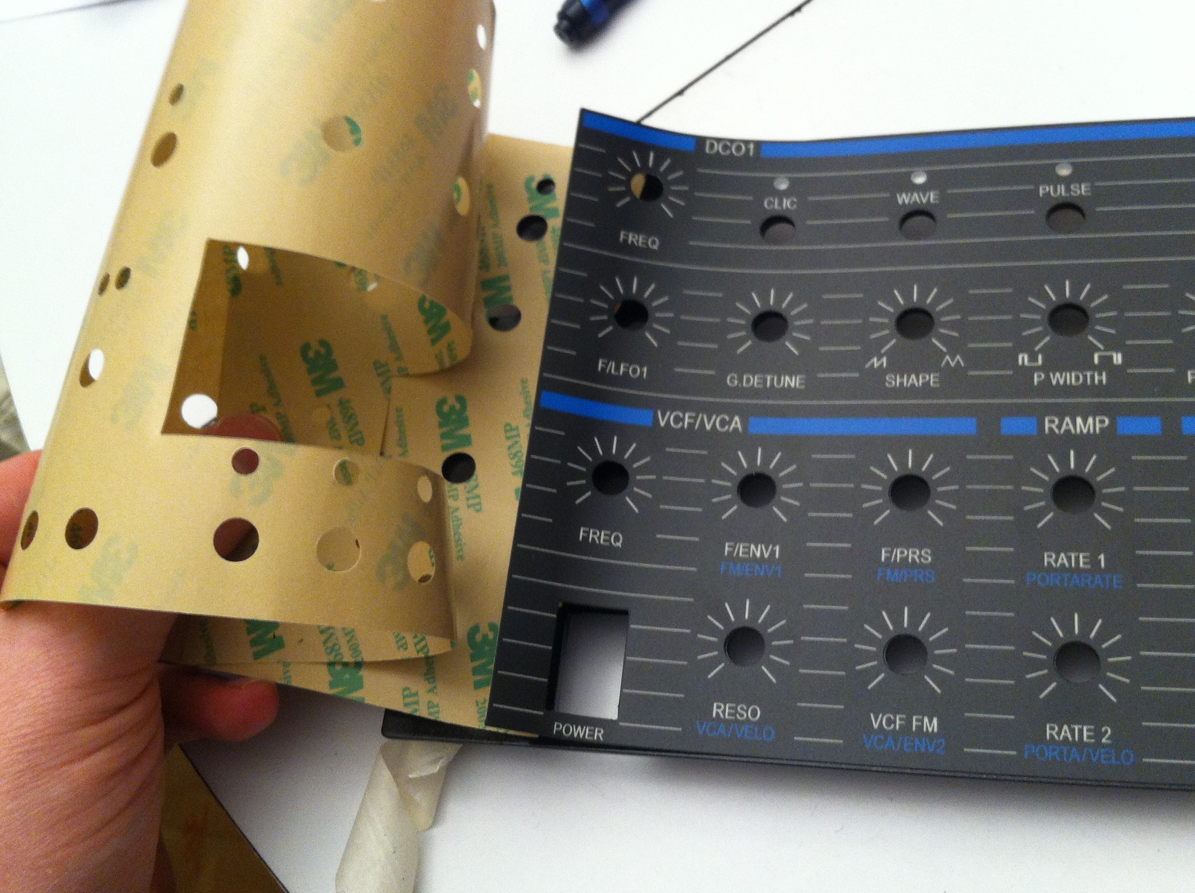
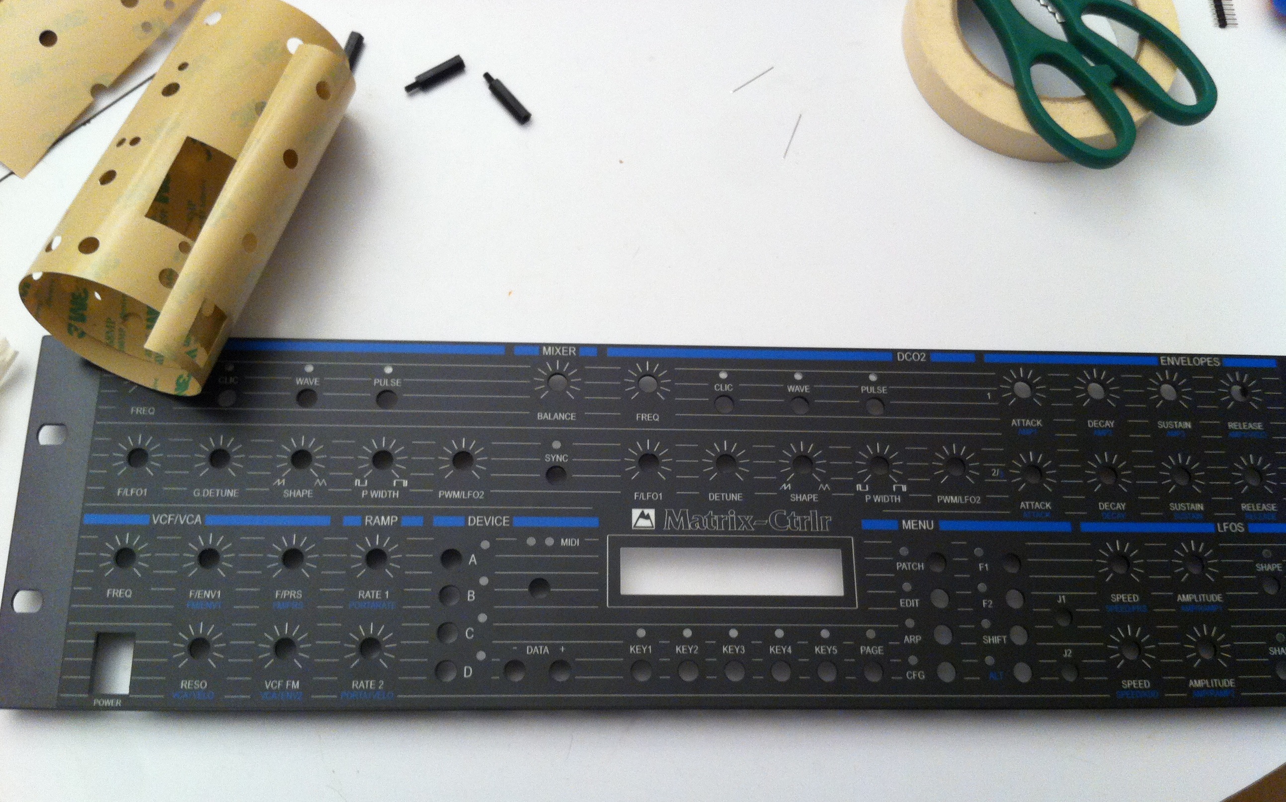
This is a one shot operation and a very critical step : take your time, be sober. Watch out for air bubbles while applying and you should be fine. 😉
Hint : don’t forget to remove protective plastic sheet from the LCD display. You can give a nice finishing touch on the overlay by brushing holes (softly) and sides with a used toothbrush to remove glue dust.
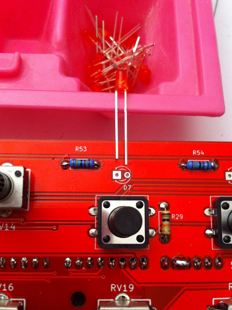
Step 20 : LEDs (critical)
 D, D, … D

Remove the front panel (yes, again).
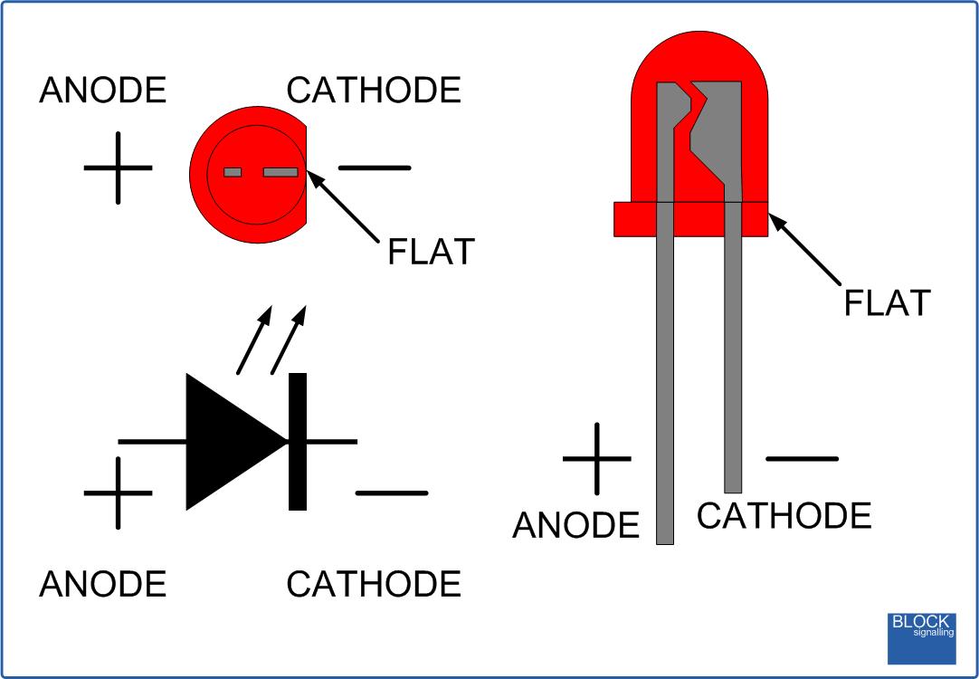
Observe the LED orientations.
Place a LED in each footprint.
Flip the PCB back over and push each LED in its front-panel hole without forcing through the LEXAN overlay.
Use a Blue LED for ALT (convenience)
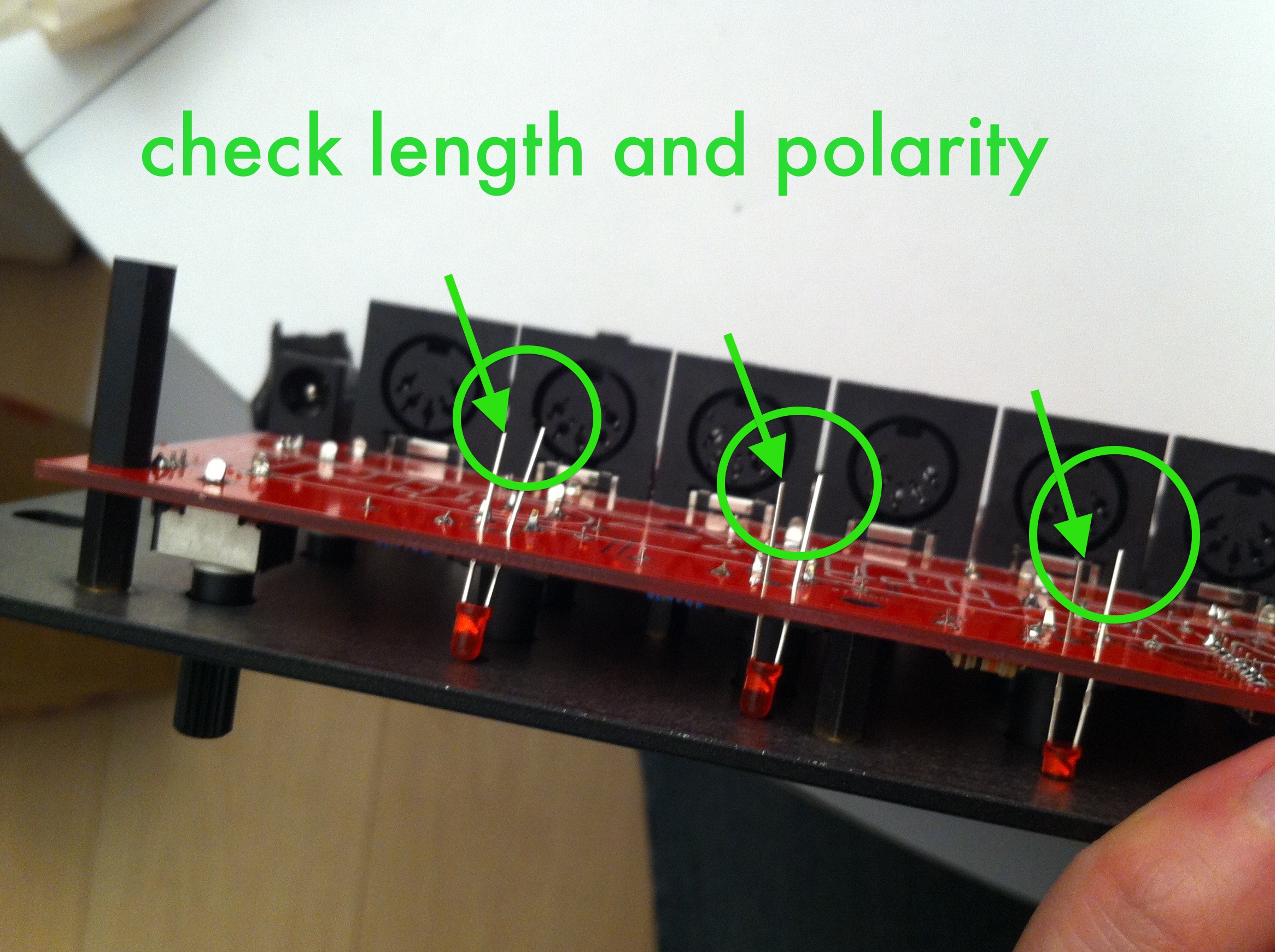
Solder only ONE lead of each LED and test they are oriented correctly.

Power up the Matrix Ctrlr. There is a boot test sequence which will flash each LED once.
Enter test mode to check each LED by pushing the unsoldered lead to the PCB with your finger. If a LED doesn’t work, you will have to remove it and re-solder it with the correct orientation ; that’s why you soldered only one lead.
Once all LEDs are OK, you can finish soldering and use your cutting pliers.
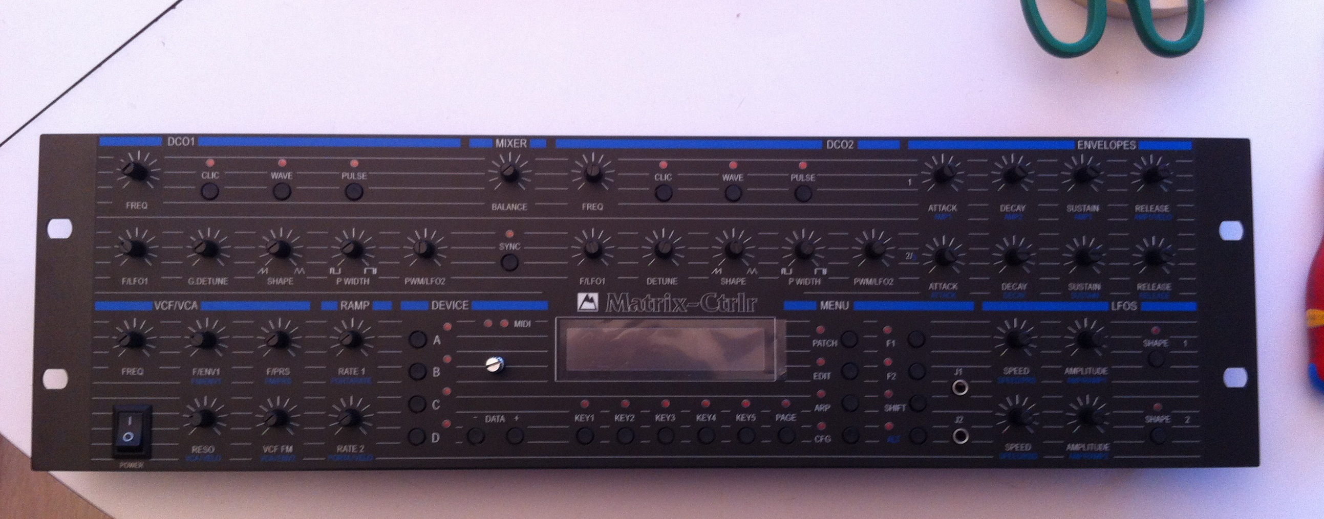
Step 21 : Final stage
KNOBS
Notice there are 2 screws hidden below the arduino board. Don’t forget to screw them in. Remove 8 M3 screws and replace them with 20mm spacers in the 4 corners.
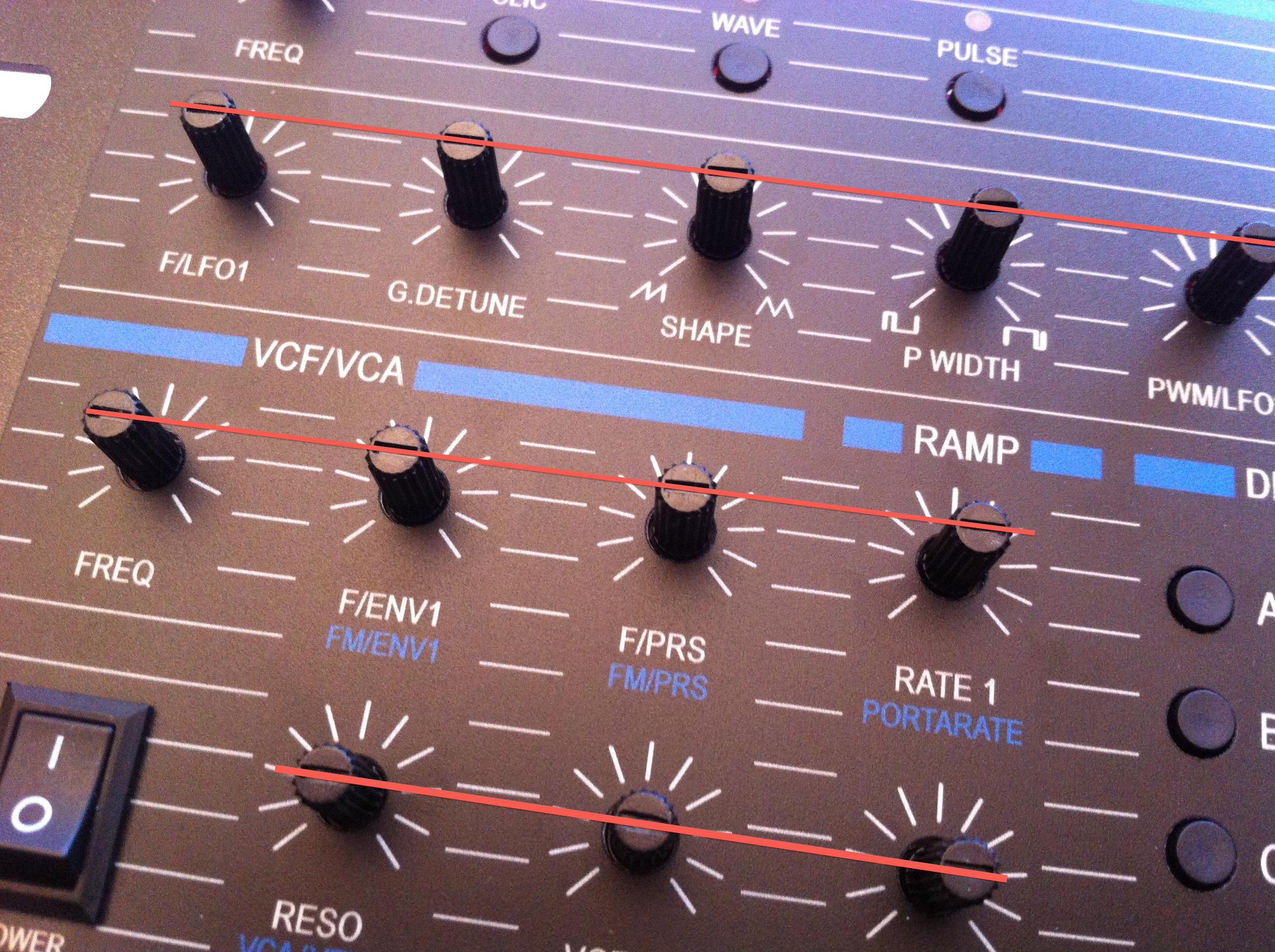
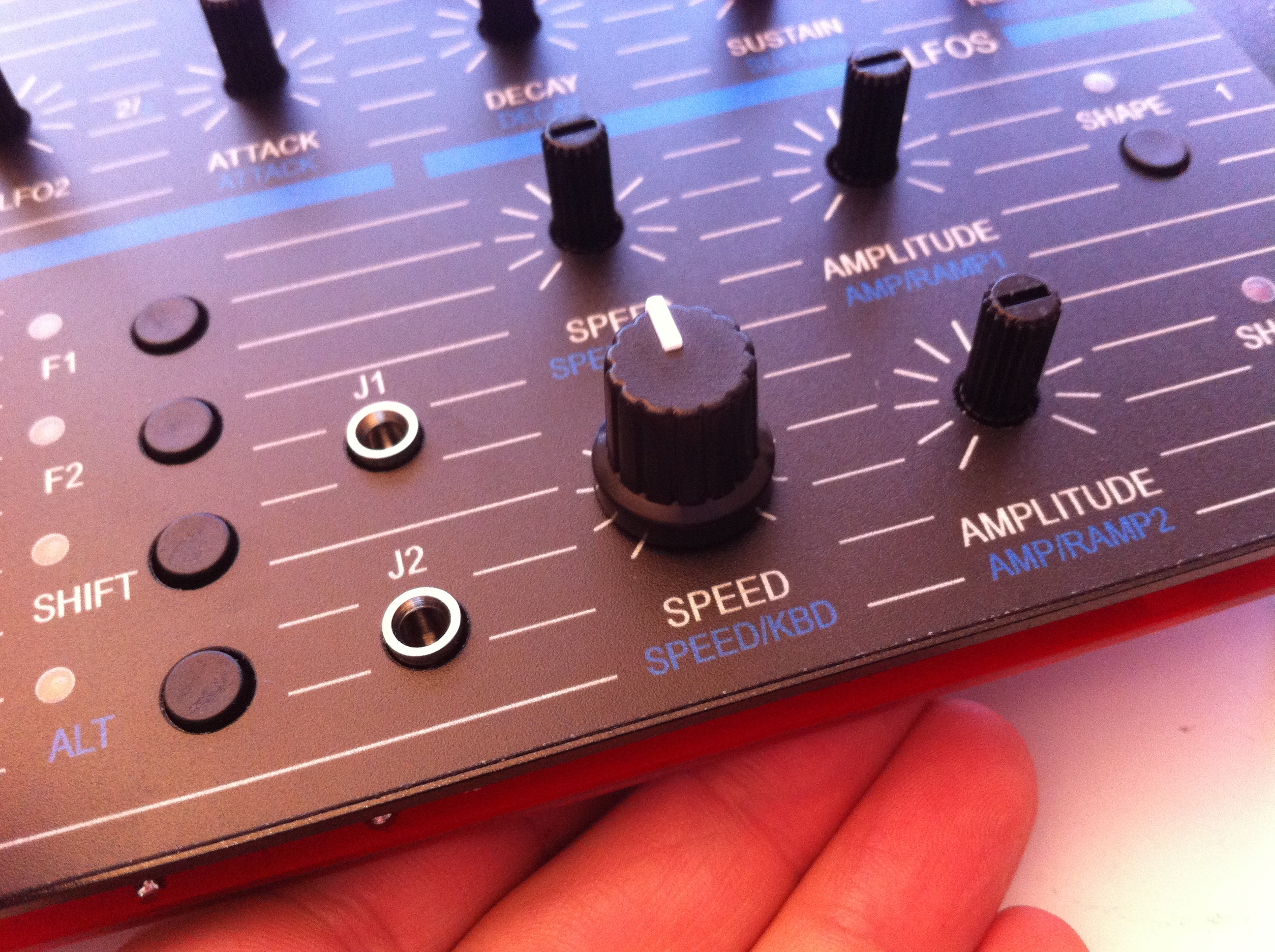
Align all the potentiometer’s axes and put knobs on them and the encoder. Don’t push down too hard and check they rotate 270°.
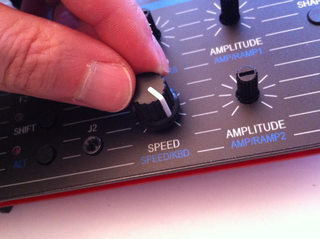
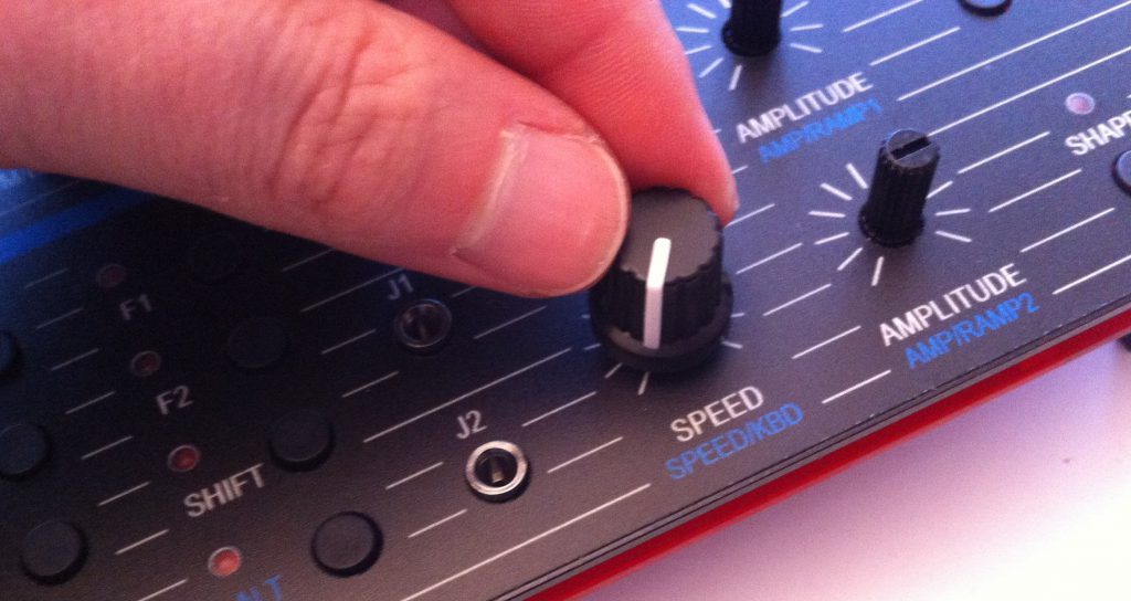
Careful: the knobs snap on and are hard to remove.
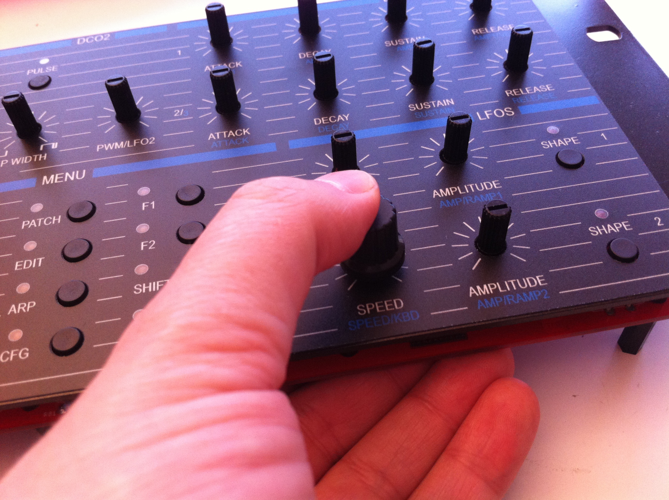
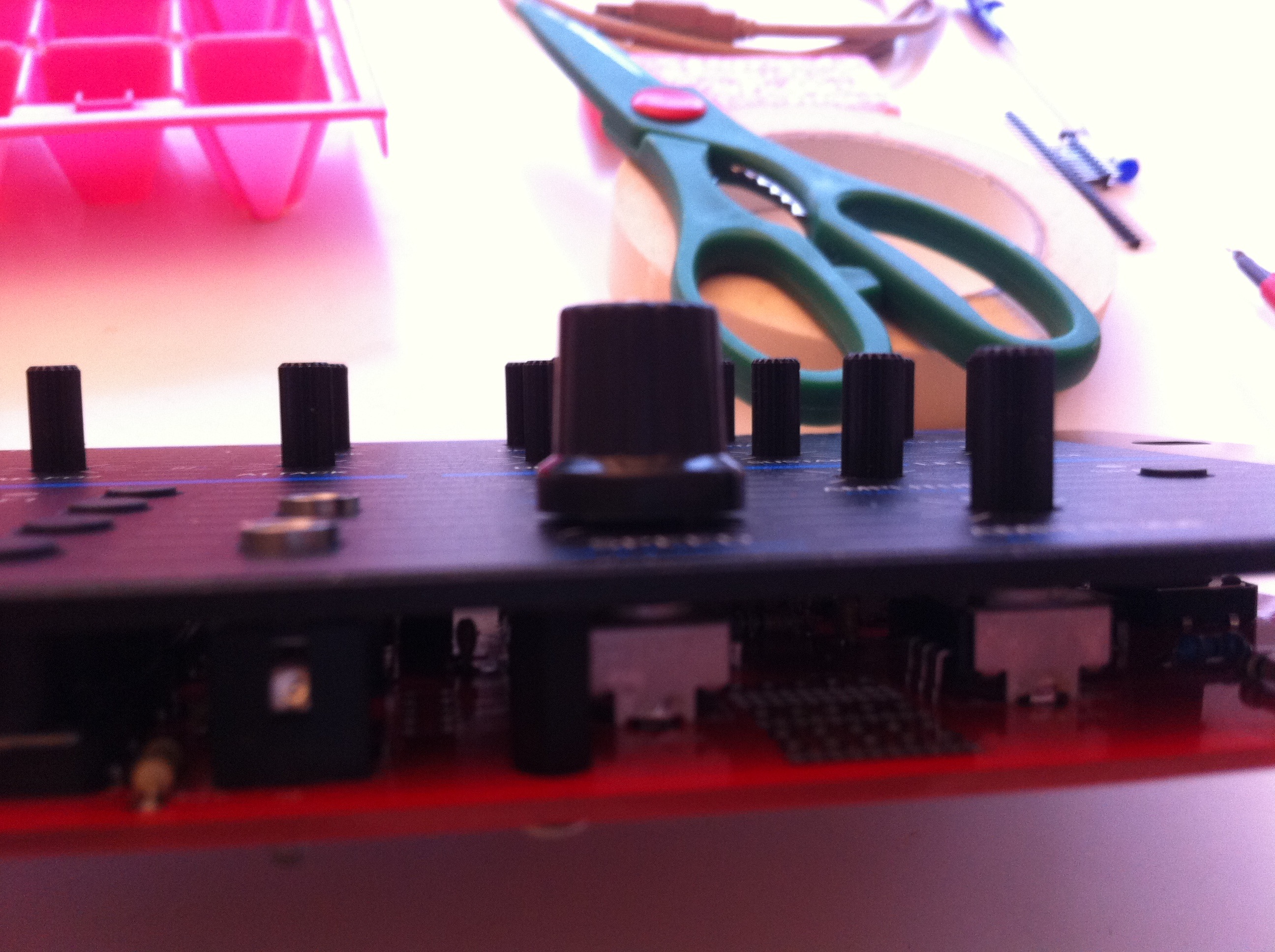
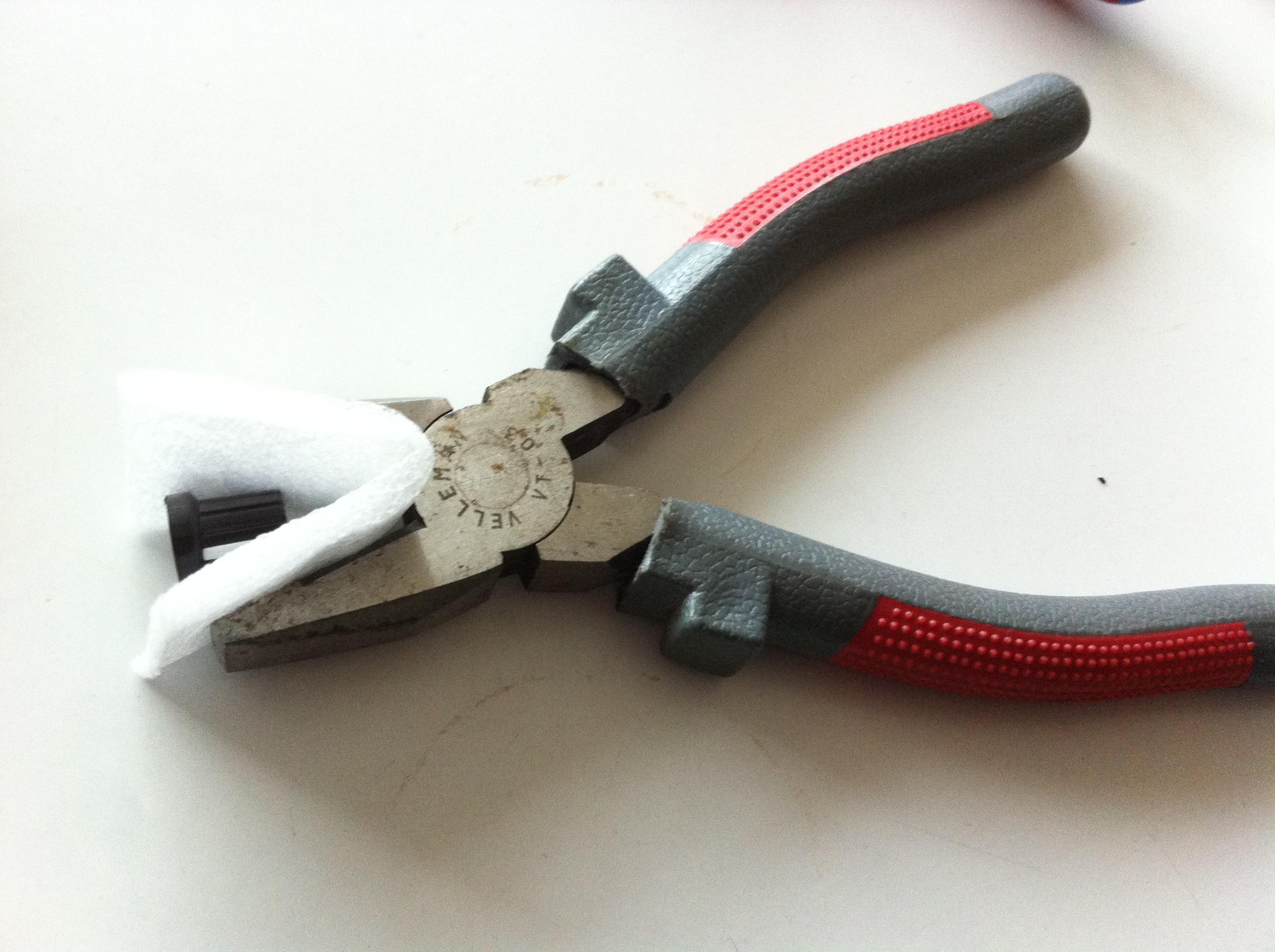
TIP : Remove a knob easily by pulling it with a strong pair of pliers with some foam for padding.
If you’ve got a back panel or an enclosure, it’s a good idea to mount it now using the 8 removed M3 screws.
Finished !
Enjoy your Matrix Ctrlr and check out the User Guide section.
A Test Mode has been implemented to test the good behavior of the interface.
You will need to set up the system in the CFG Menu.
Nota : DL1 & DL2 are two optional LEDs used to pimp the inside of your Ctrlr. They are connected to a +5V line through a 330 ohms resistor. They can be left free (useless).
