![]()
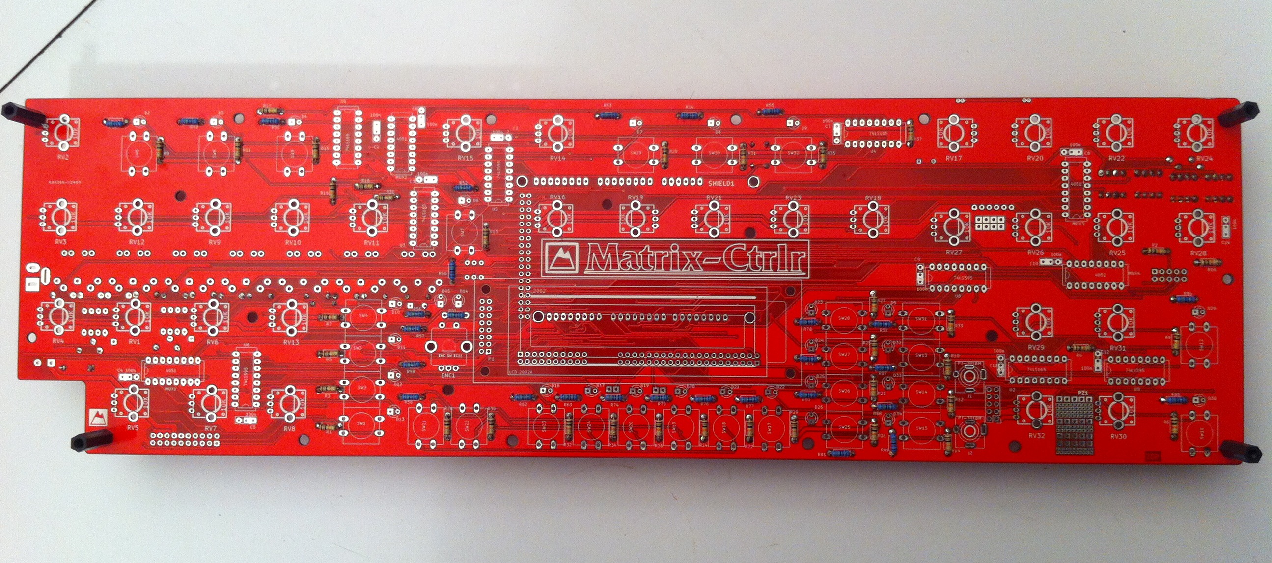
You will need to solder both the TOP and BOTTOM sides of the PCB. Take your time and examine the unpopulated PCB and schematics in order to understand where each part is located. Schematics are located in the resources section.
Please read the whole instructions first (soldering + assembly) to prepare your job. You can ask support if necessary.
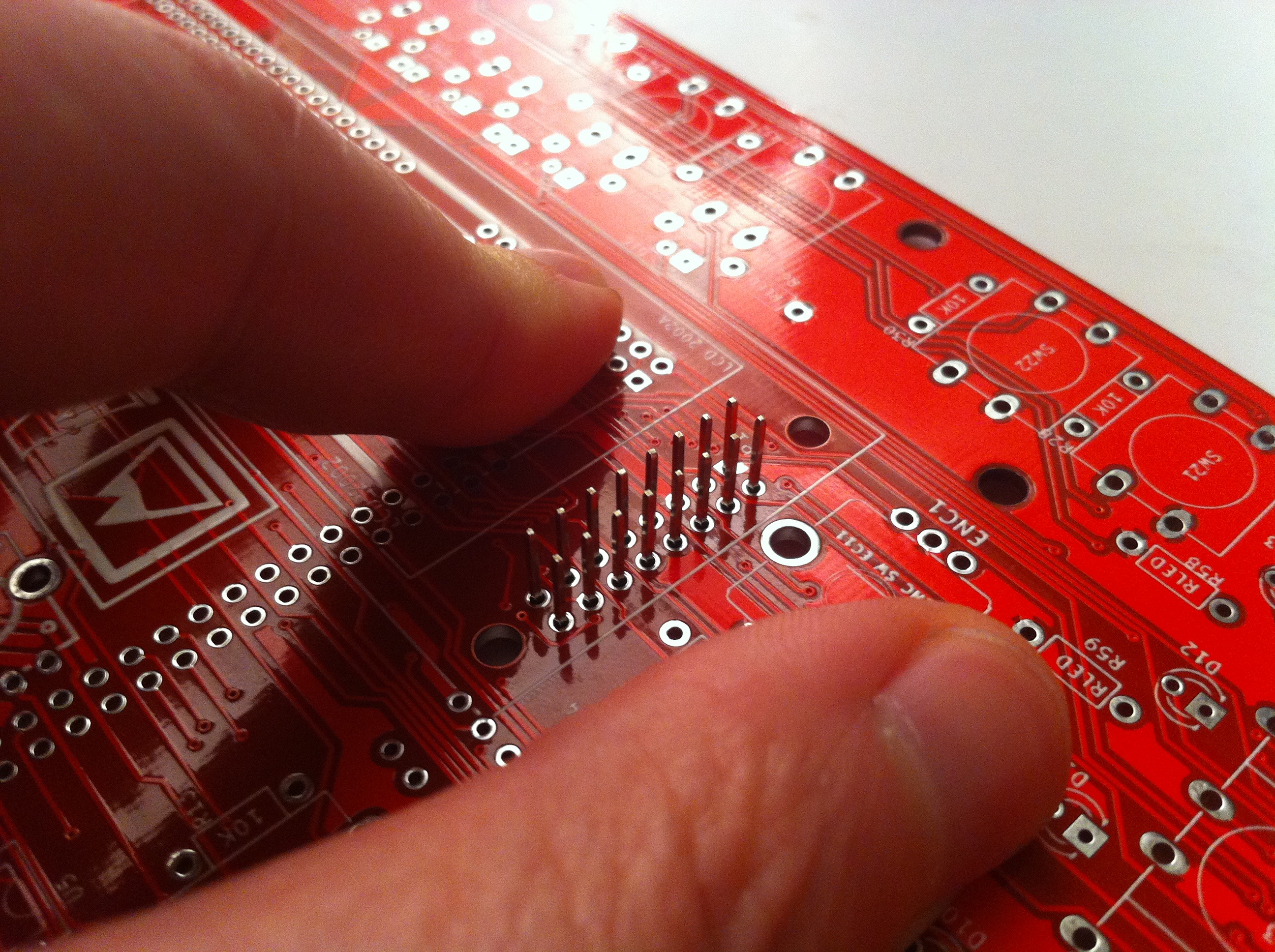
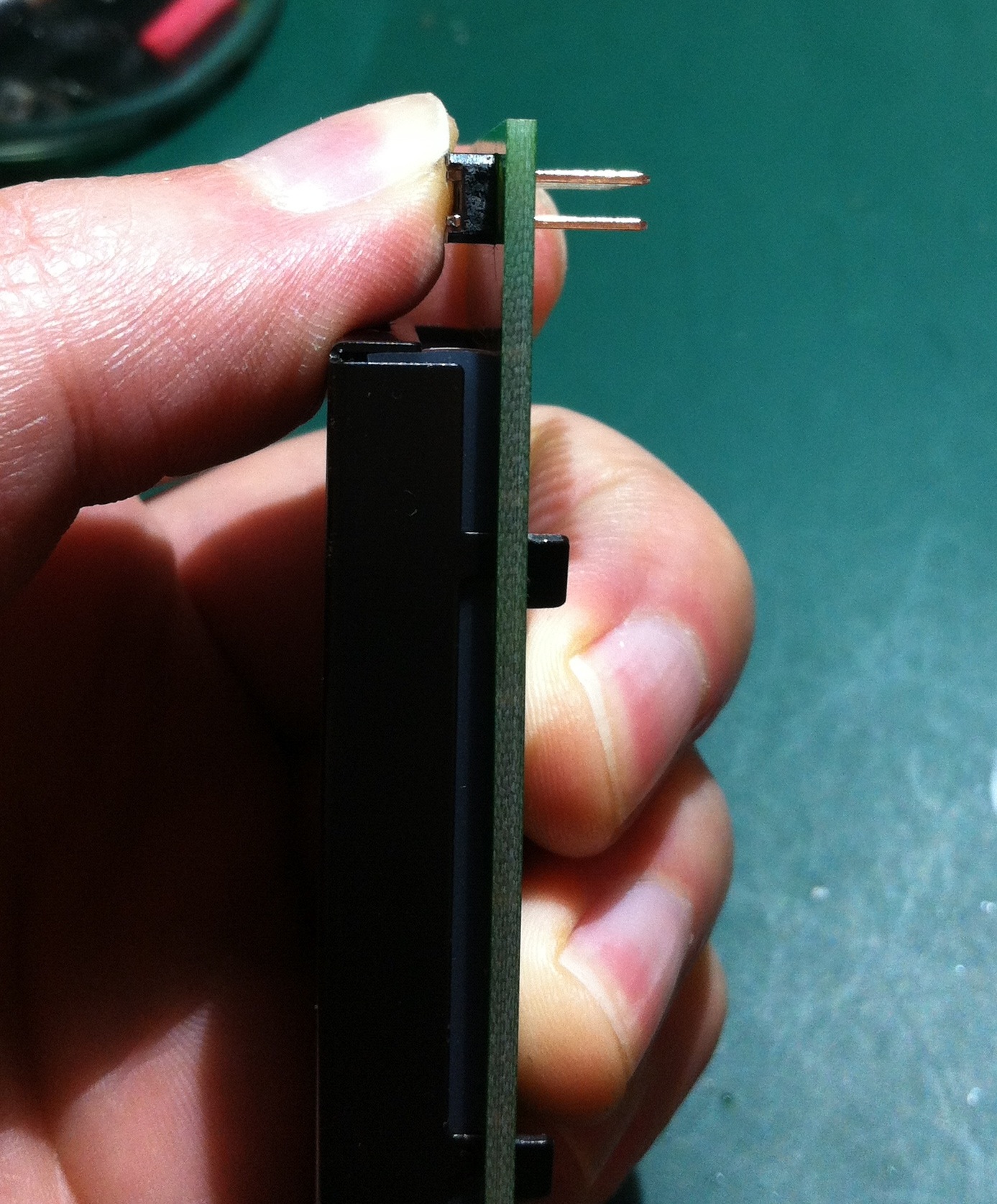
Step 0 : prepare LCD DIL connector
2X40 PIN-HEADER
Cut a 2×8 connector from the dual pin-header and use the PCB to push on the plastic as on picture below. Put this connector aside as it will be used for the LCD later in step 15.


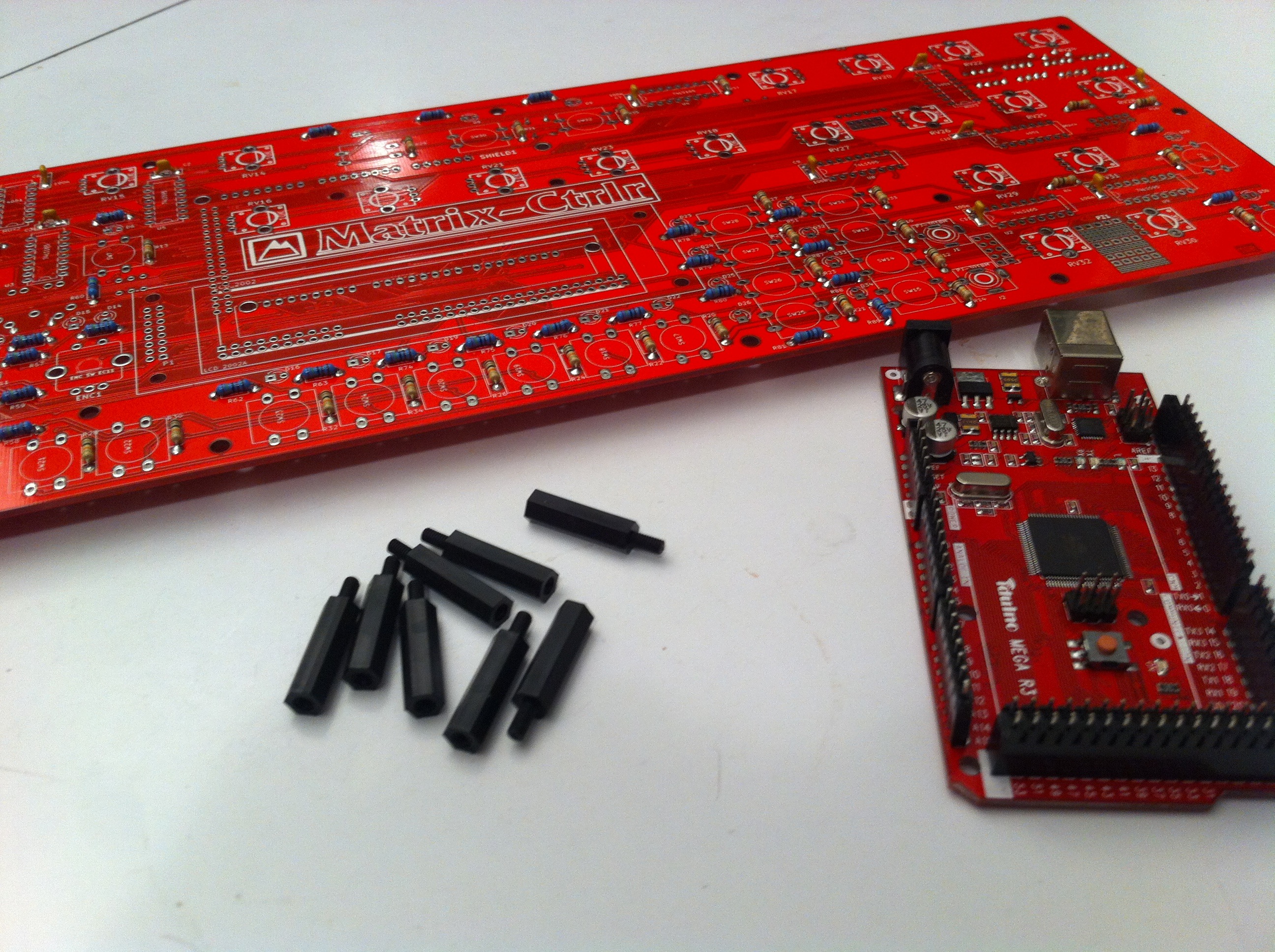
Step 1 : attach 20mm spacers
8 x black spacers
Use 2 spacers at each of the 4 corners of the PCB. This allows you to insert and solder components from the top.
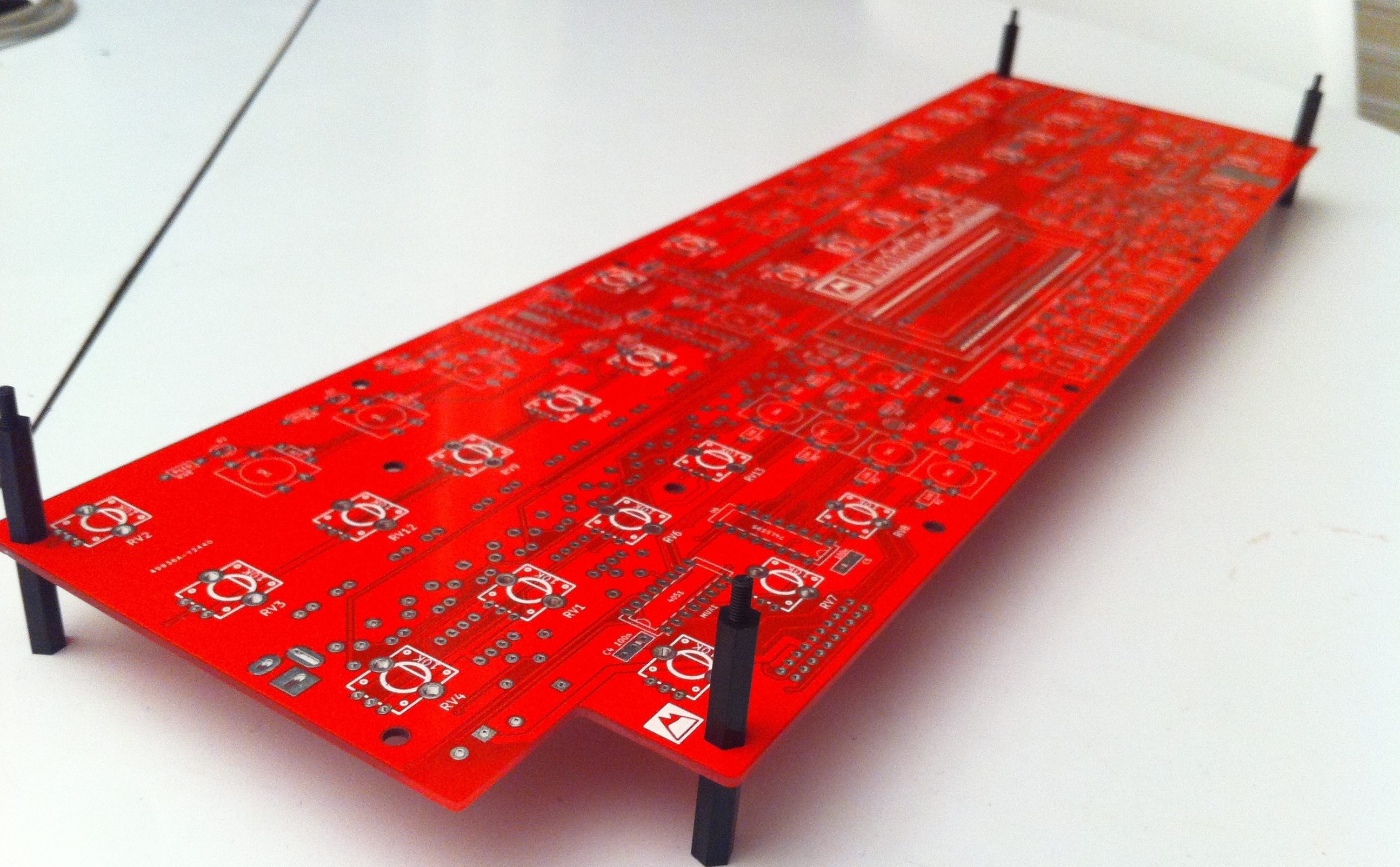
TIP : this way, you prevent the components from falling when you flip the PCB over, which will save a lot of time!
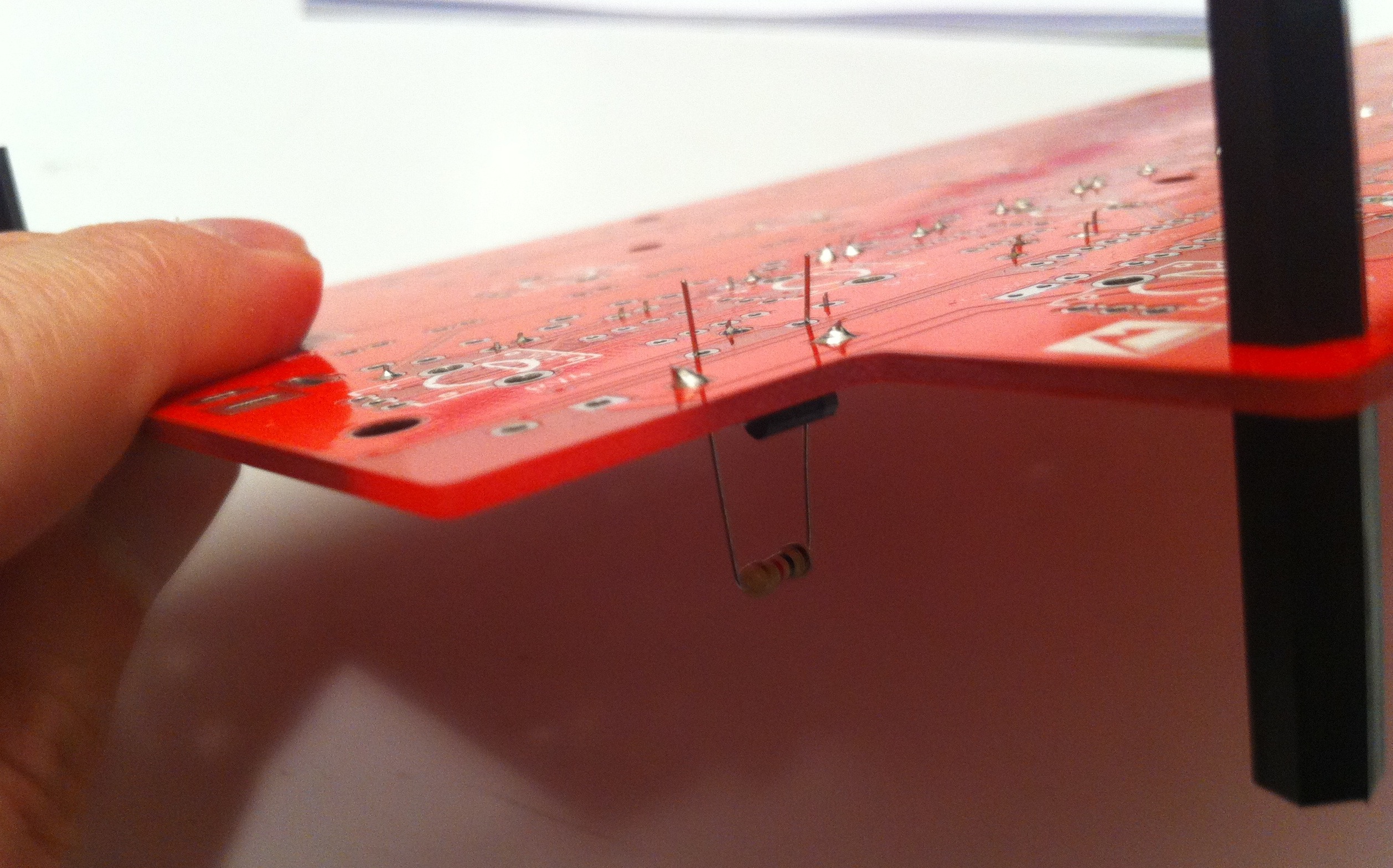
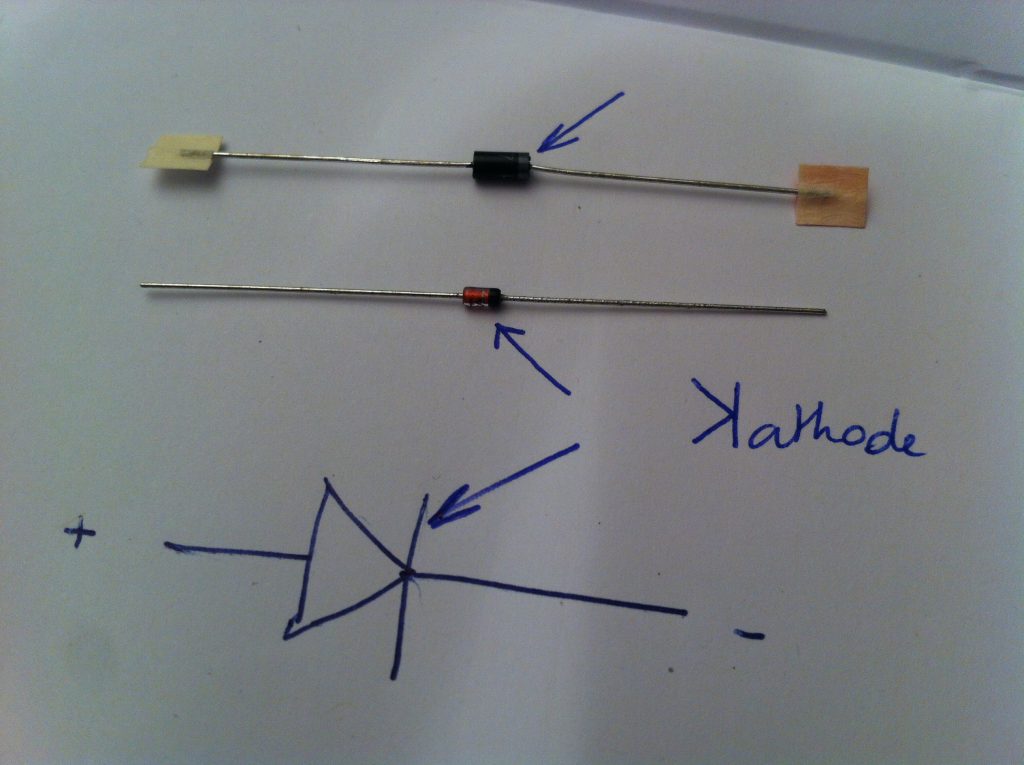
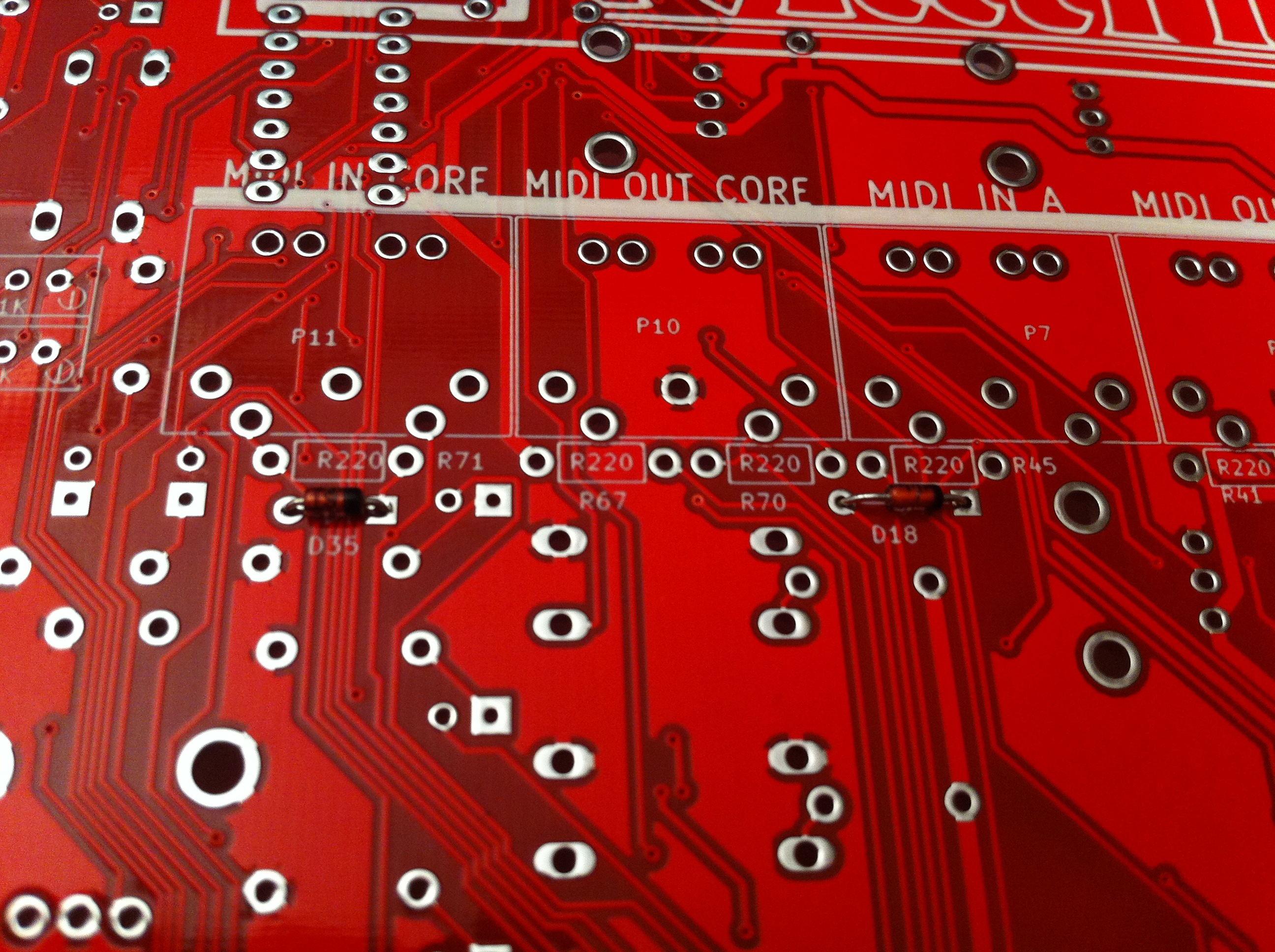
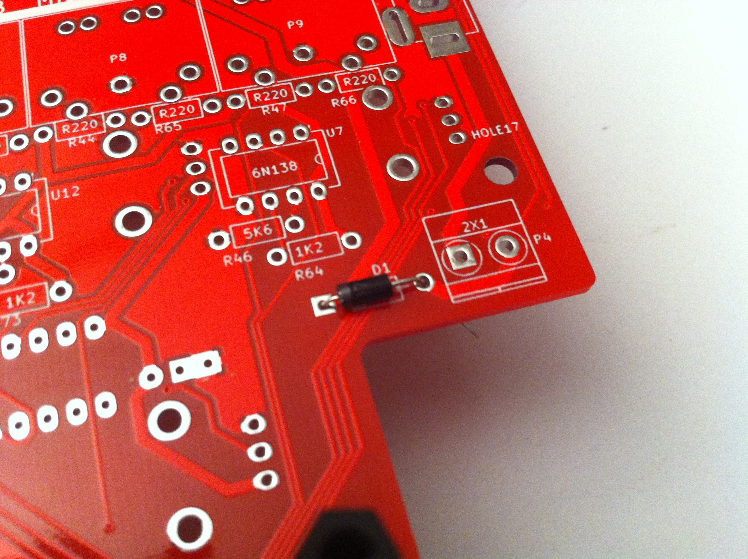
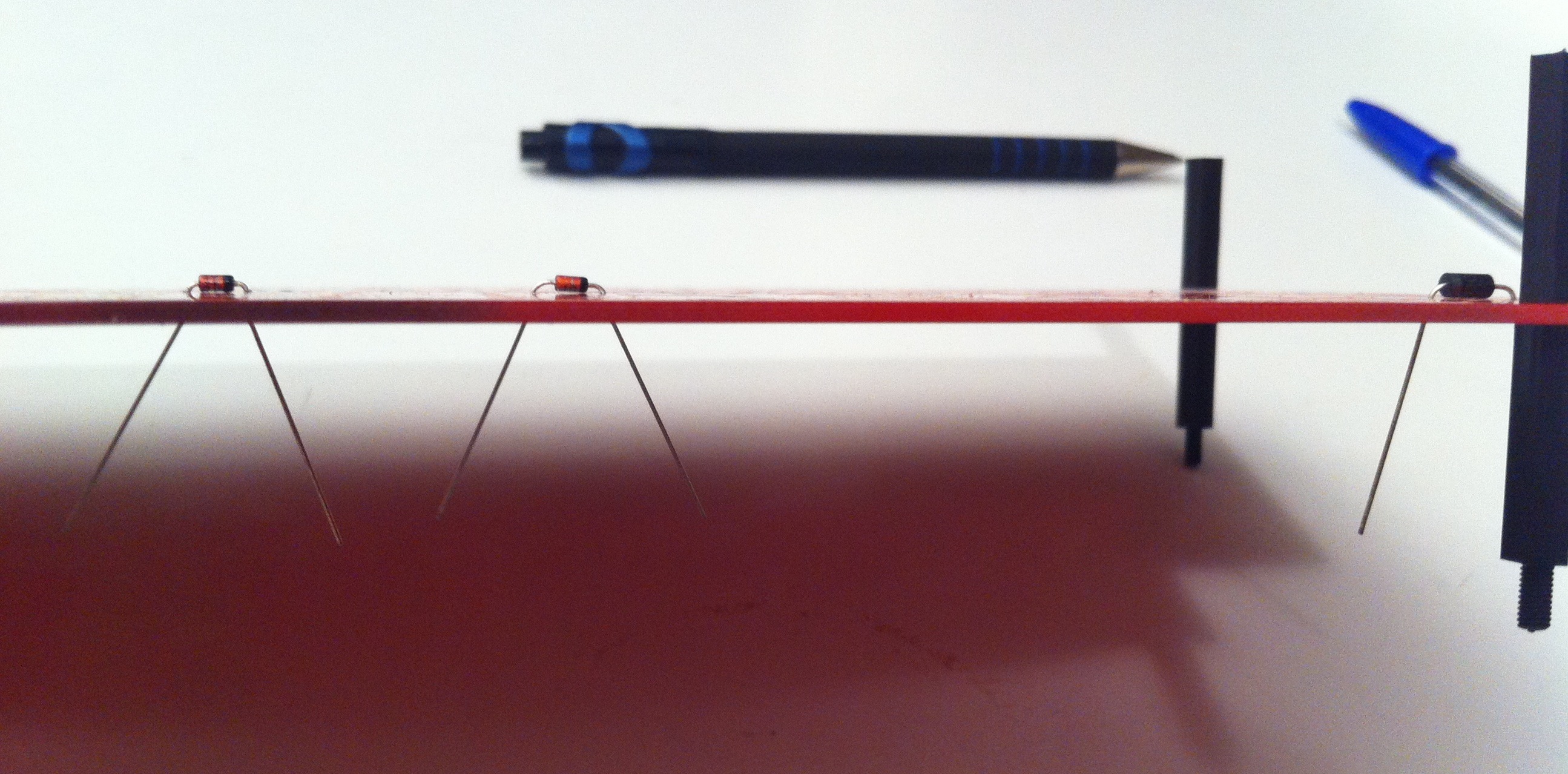
Step 2 : Diodes
D1, D35, D18.
Start with the signal diodes 1N4148 and the power diode 1N4001 on the bottom side.
Pay attention to their orientation.
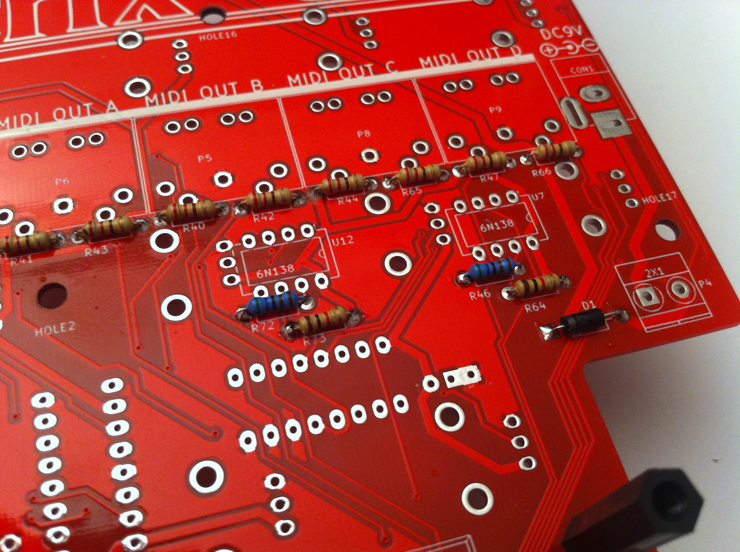
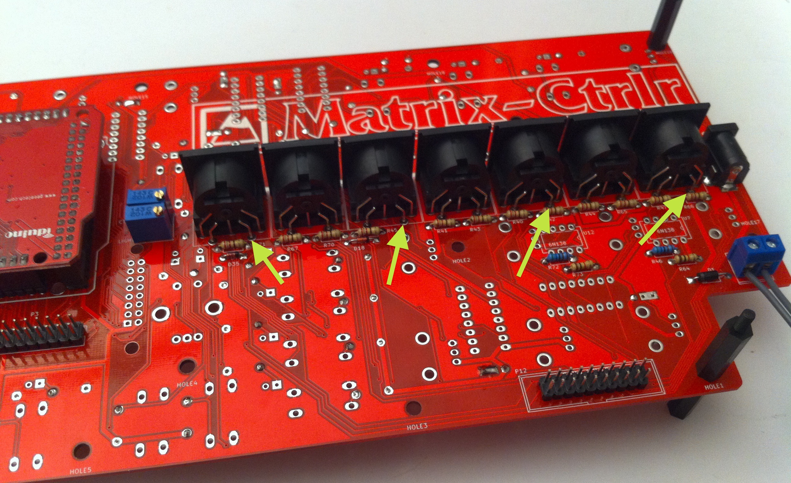
Step 3 : 220ohm, 5K6, 4K7, 1k2 resistors
R, R, …R. See partslist
Place the resistors on the bottom side of the PCB and solder them. Orienting them all in the same direction is advisable as it makes reading their their values easier. (warning : pic shows a 1K resistor not 1K2)


Step 4 : DIP-8 sockets
Solder the (4) DIP-8 sockets for the 24LC512 EEPROMs.
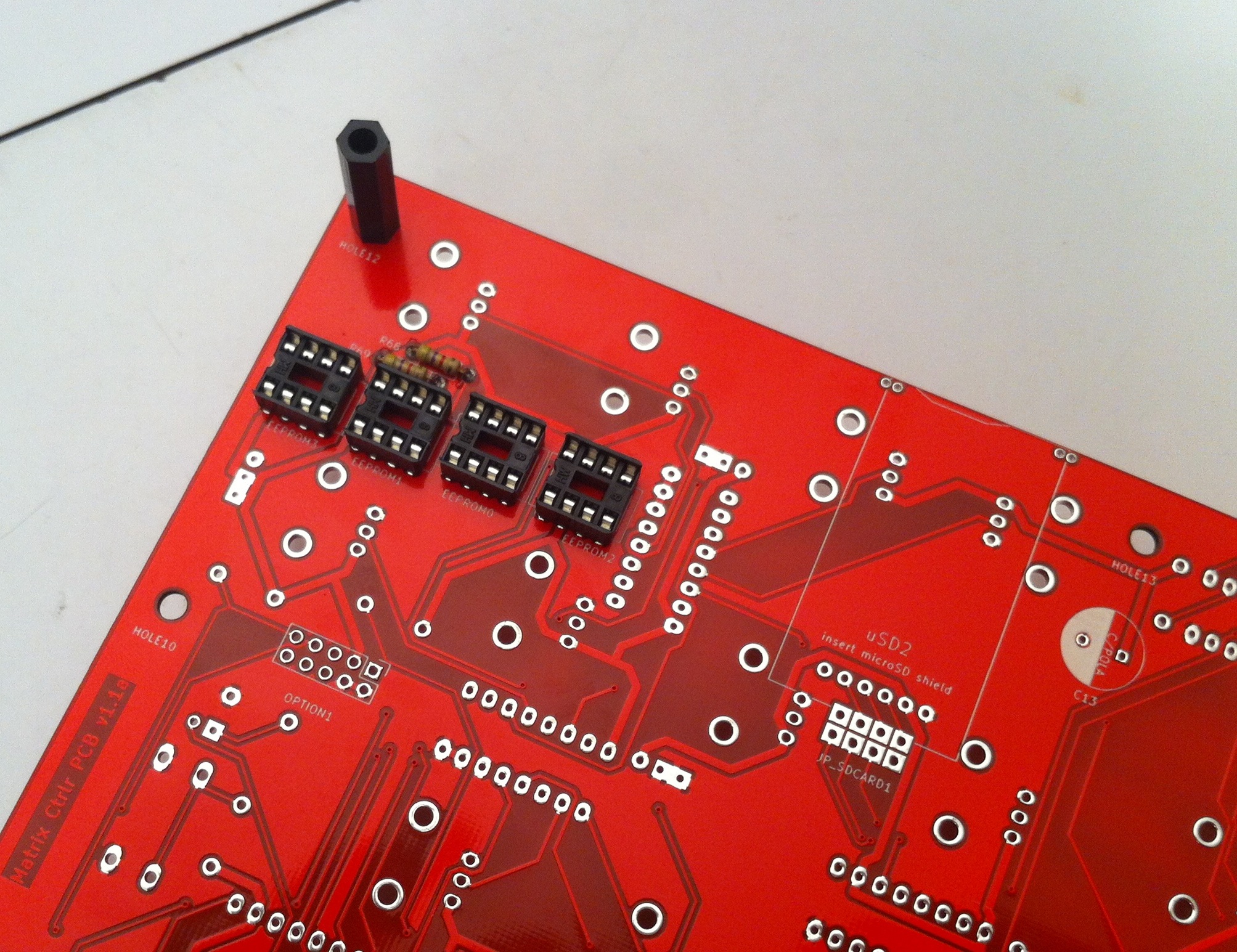

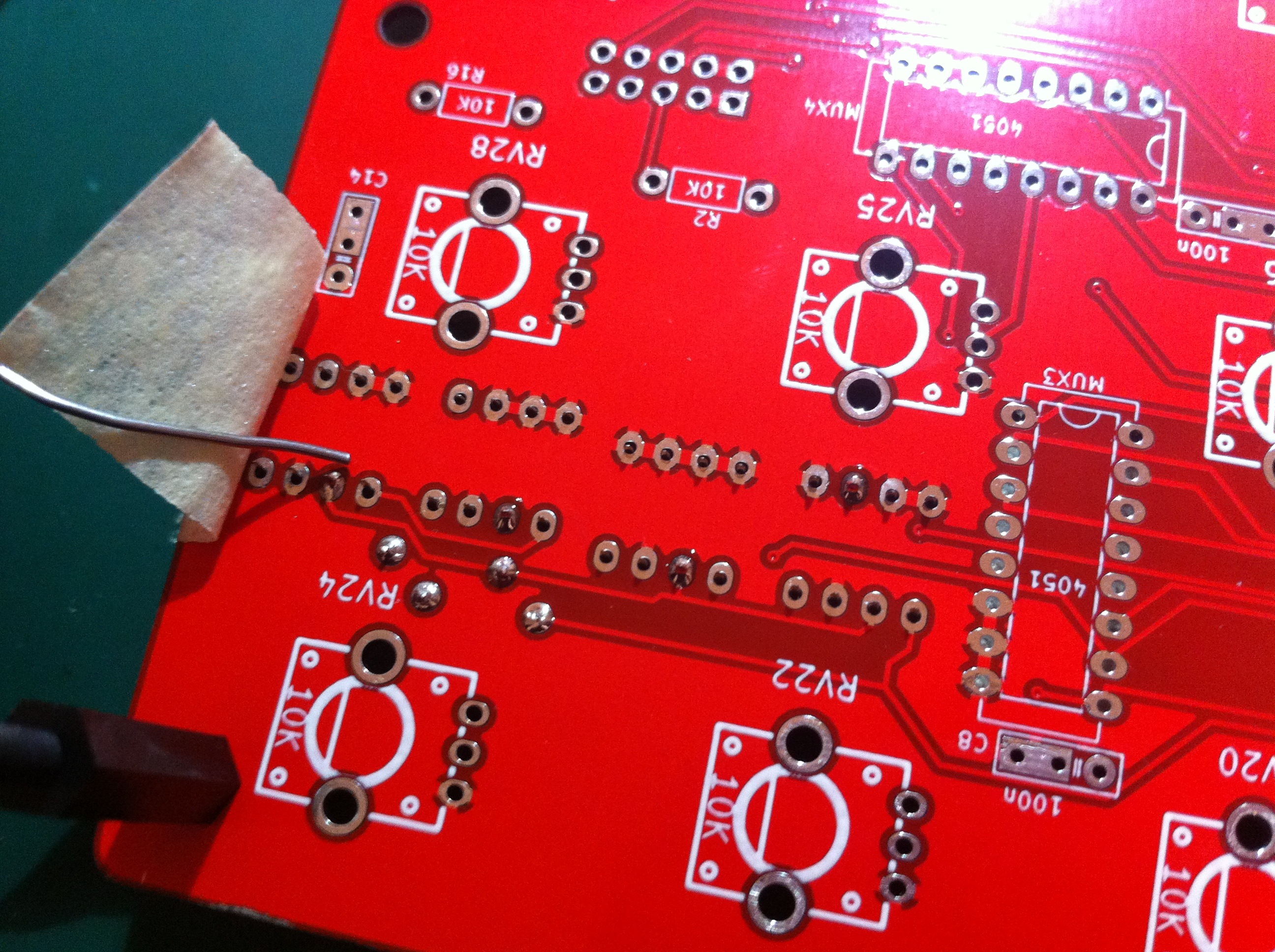
HINT : You can use adhesive tape to hold the socket in place while the PCB is flipped.
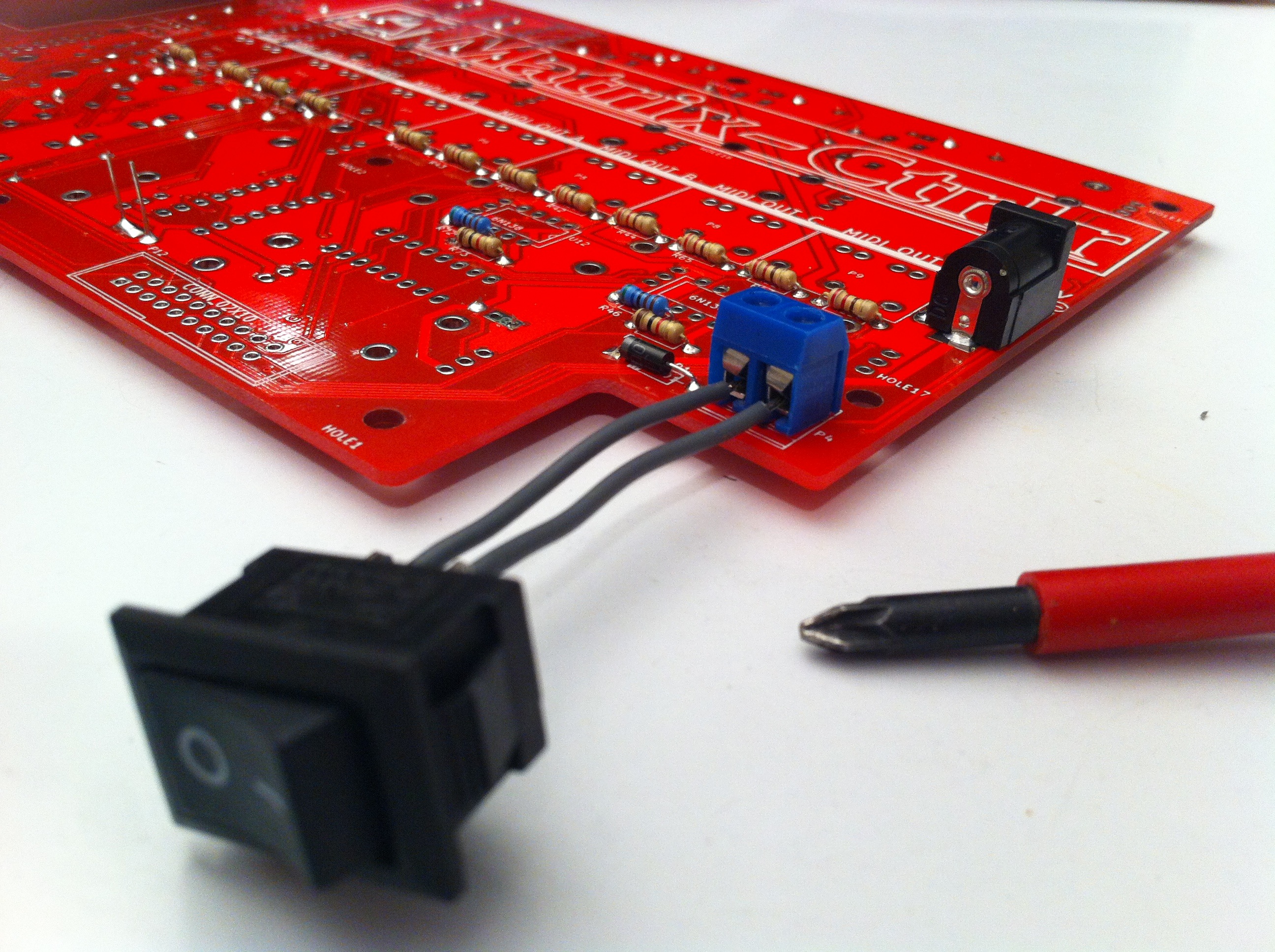
Step 5 : power plug
DC BARREL 2.1MM : CON1
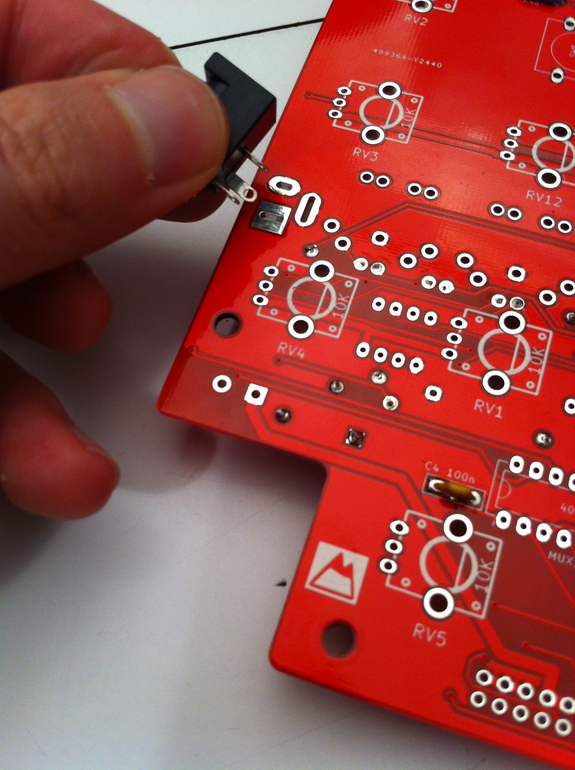
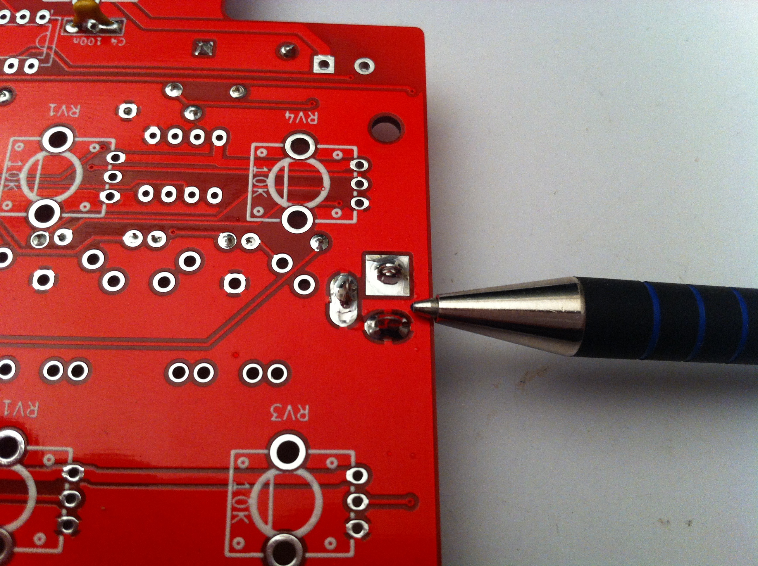
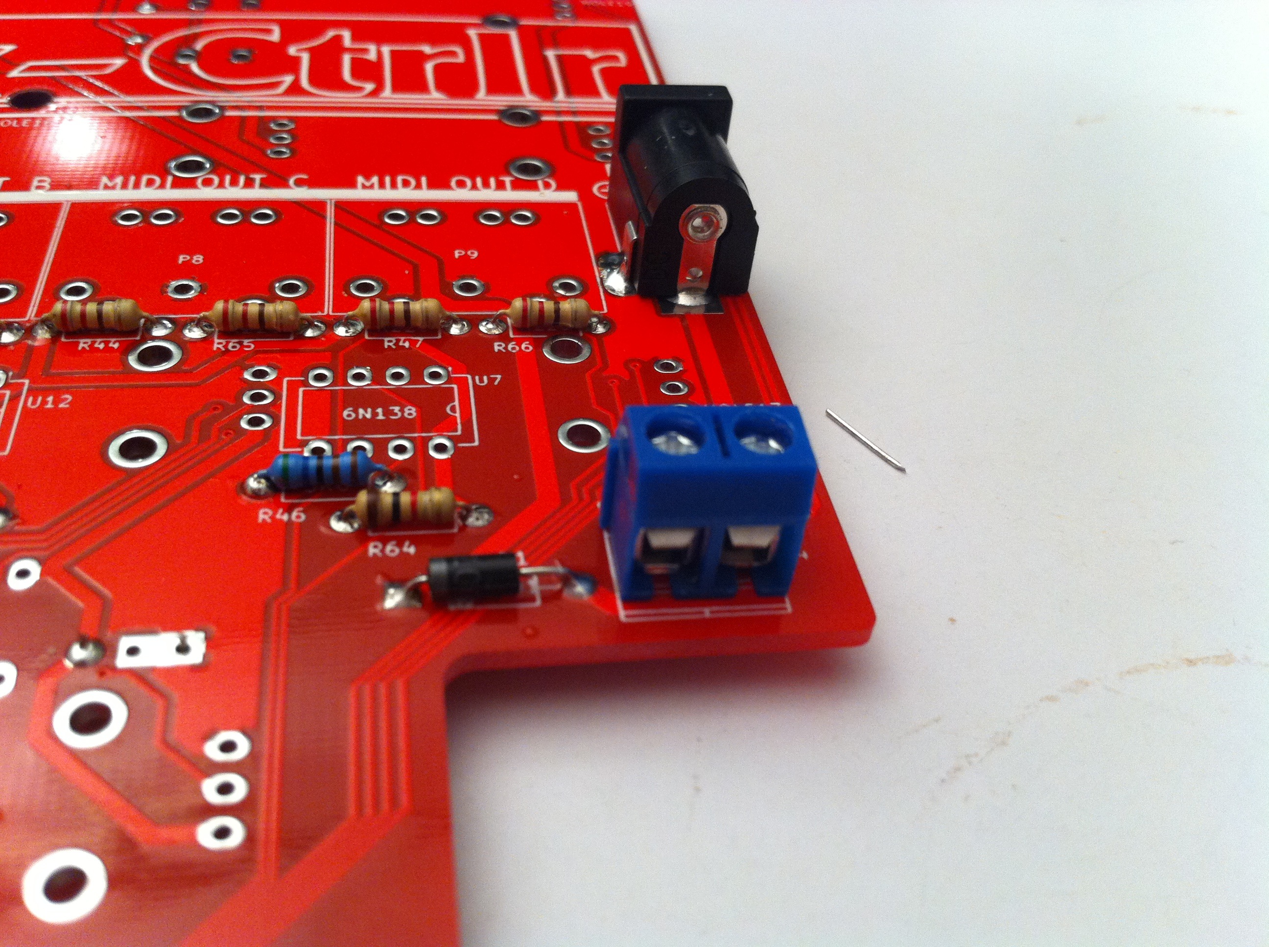
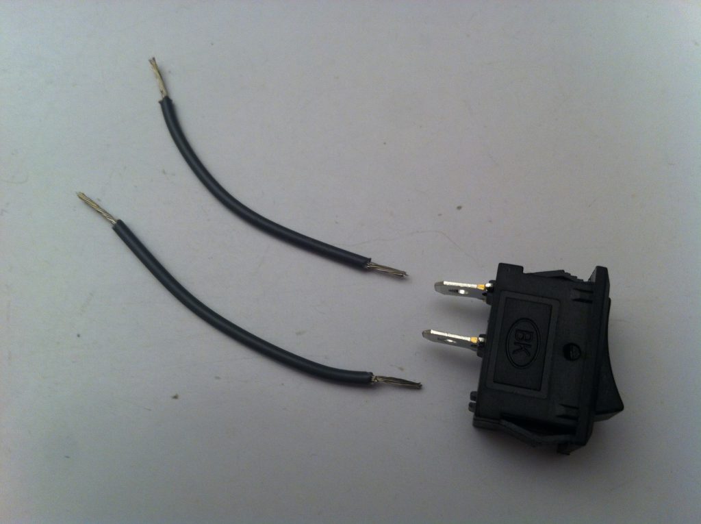
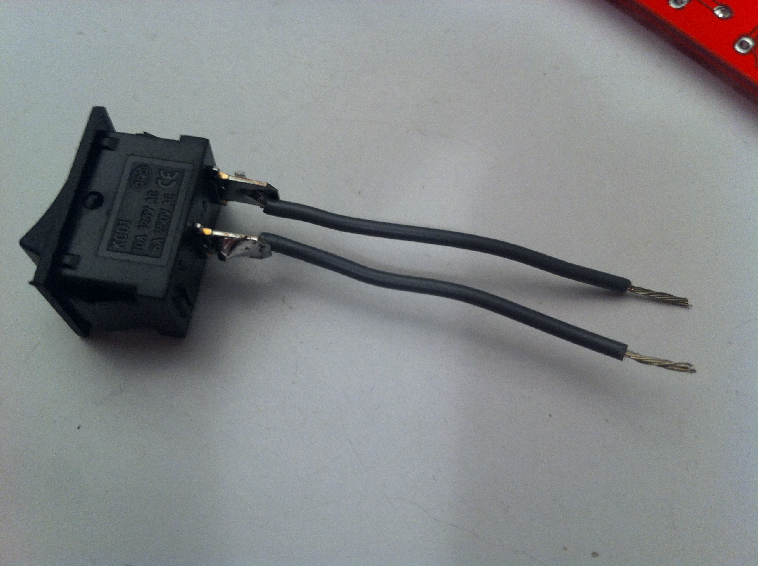
P4 : CONNECTOR FOR THE POWER SWITCH.
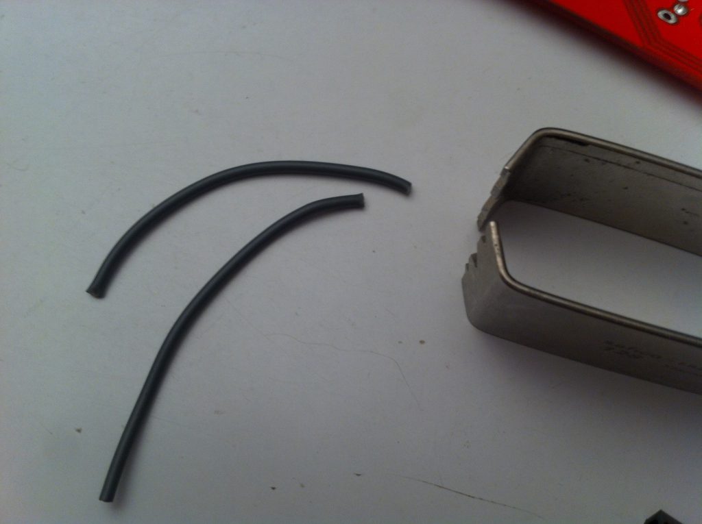
Solder two pieces of AWG24 wire to the switch as in the picture below. This will connect to P4 when checking the power supply in step 10 (Do not solder P4! Wires attach here with screws).
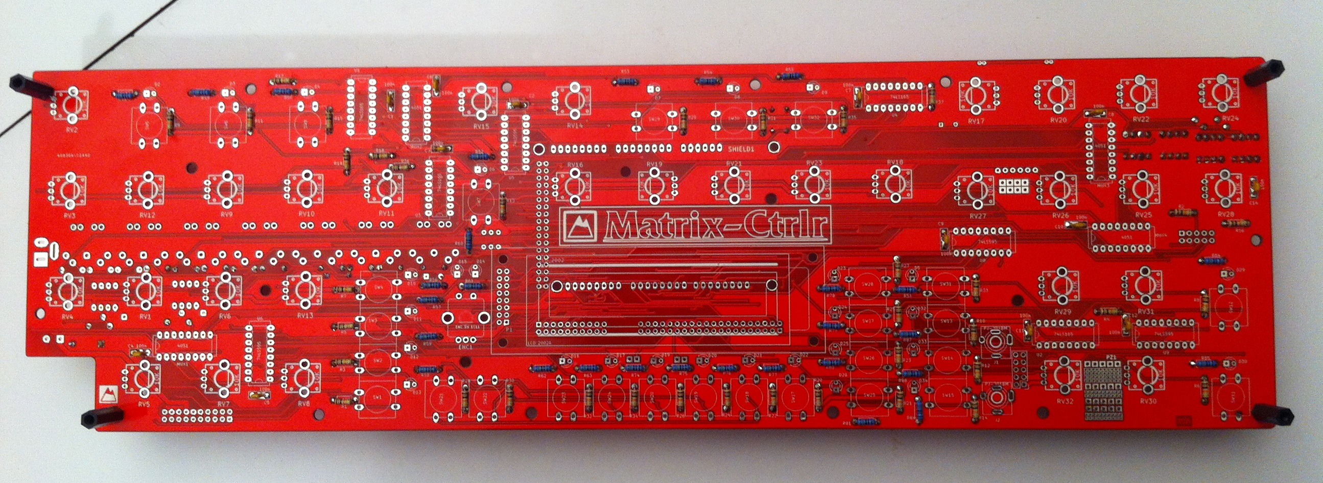
That’s all for the moment on the bottom of the PCB. Flip it over to work on the top.
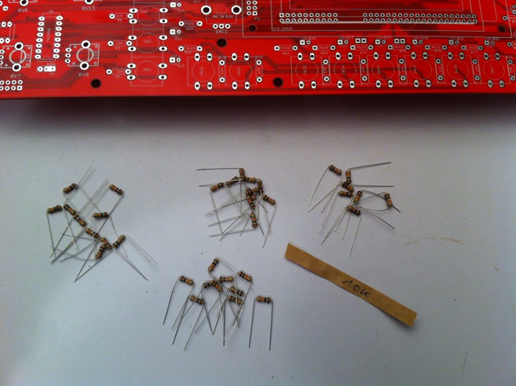
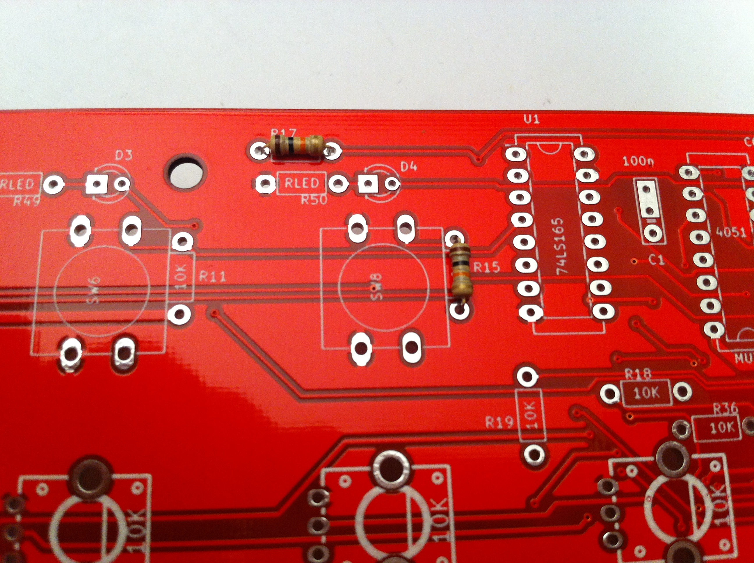
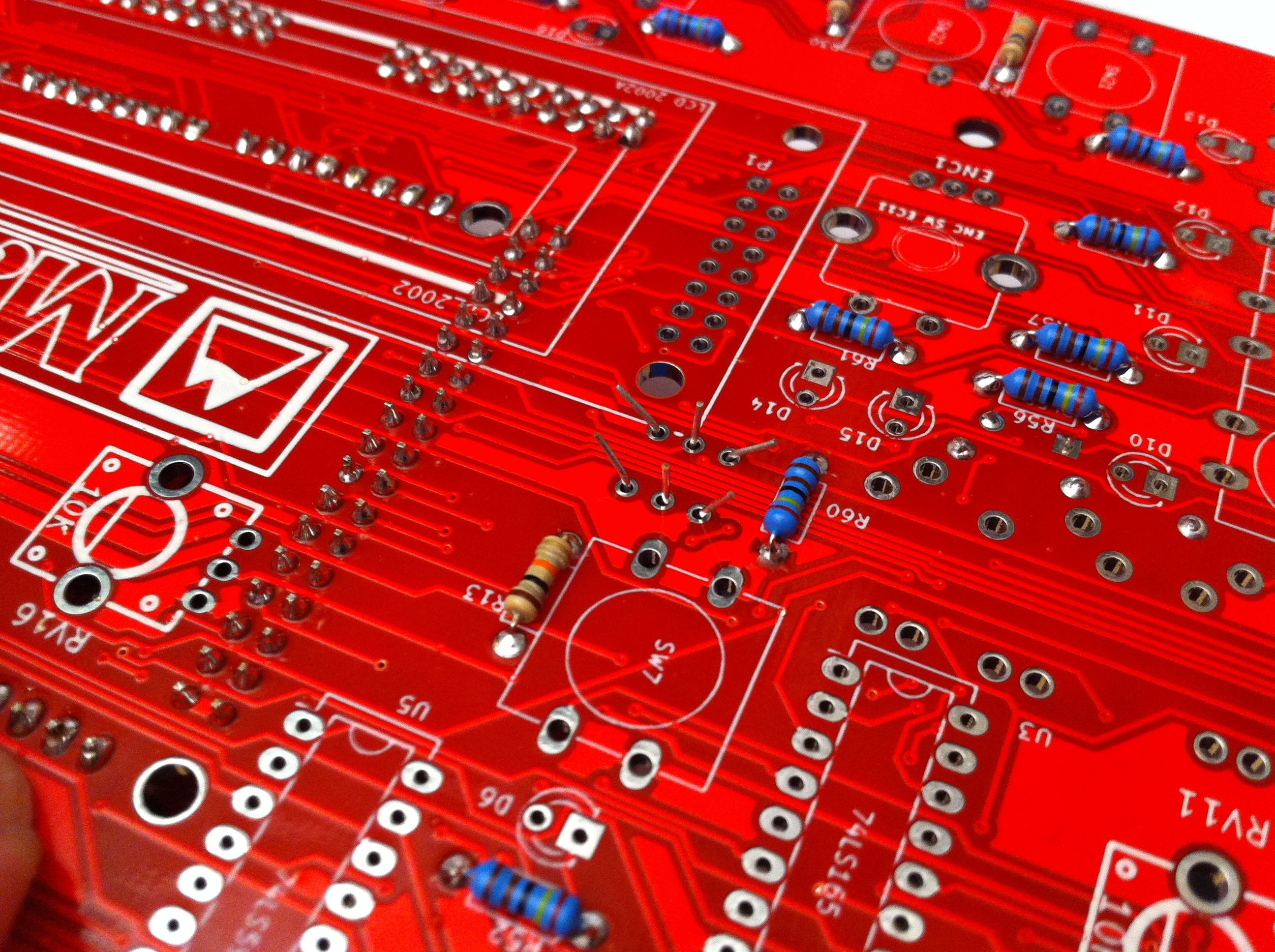
Step 6 : RLed, 10K resistors
R, R, … R. SEE partslist
Add these to the top side of the PCB.
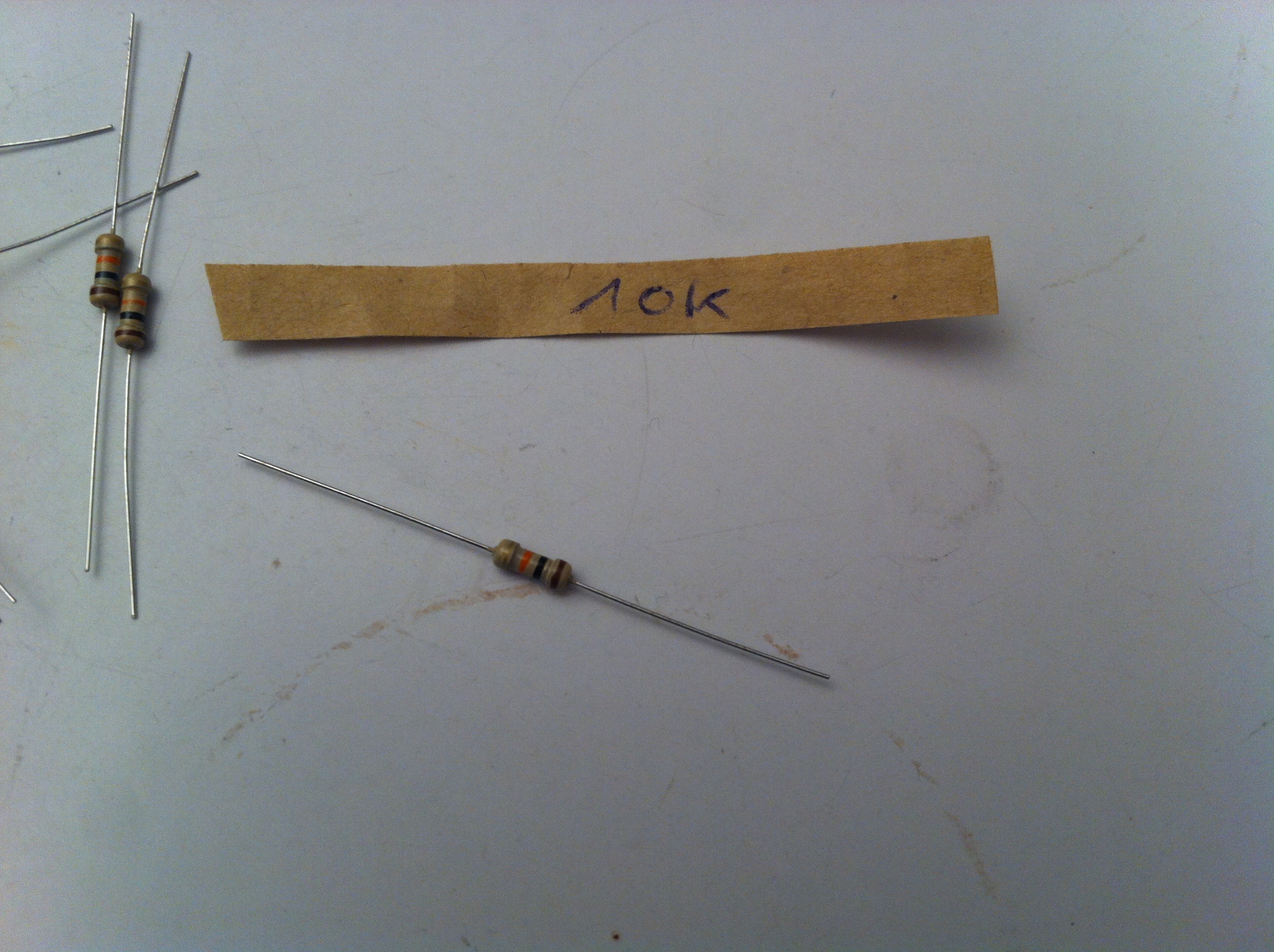
RLed = from 2K4 to 10K. With the experience it appears that a 10K value is fine, 2K4 being too bright. As a consequence all the resistors on Top of the PCB have the same value (10K). This way it is much more easier to populate the PCB.
In the picture : 2K4 at 1% tolerance means these have a different body color than the 10K ones (5%). Their orientation doesn’t matter but keeping them all in the same direction is, again, advisable. Latest kits are furnished with 70 pieces of 10K 1% blue body resistors.


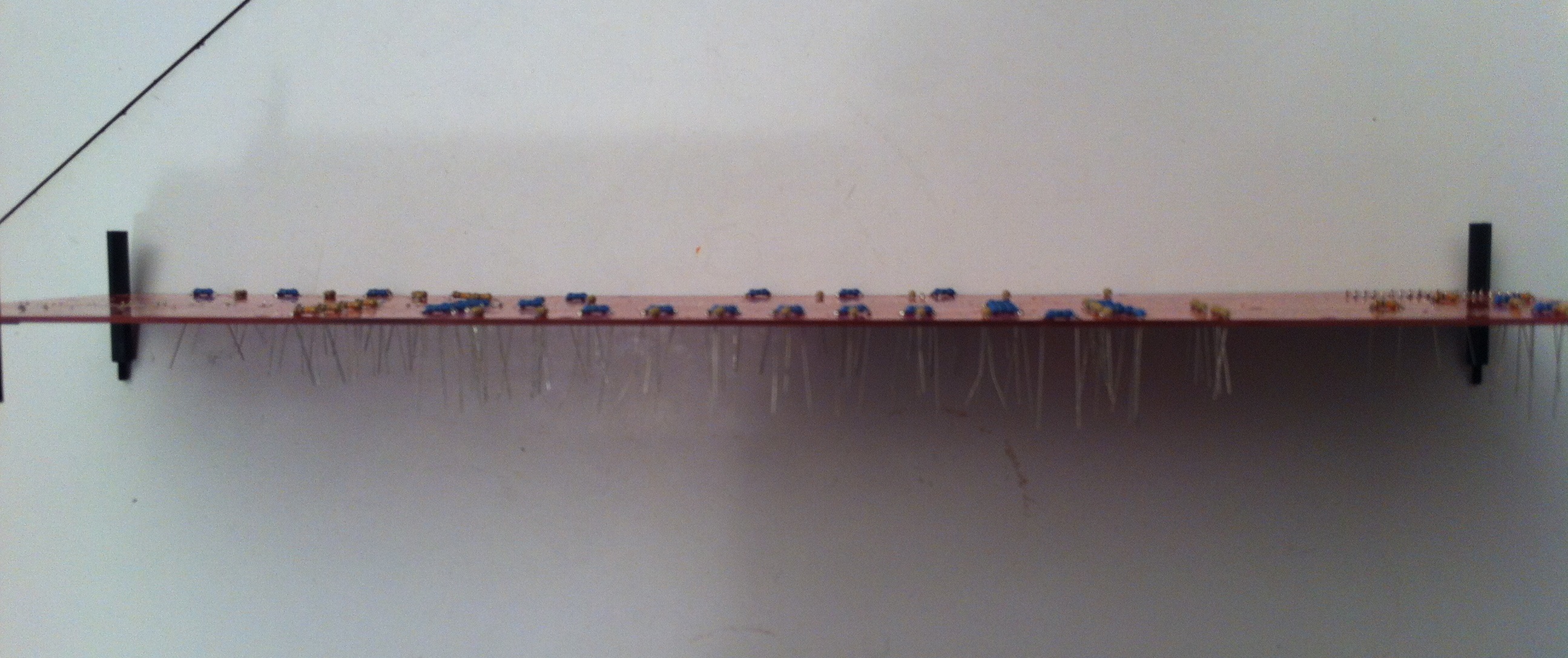

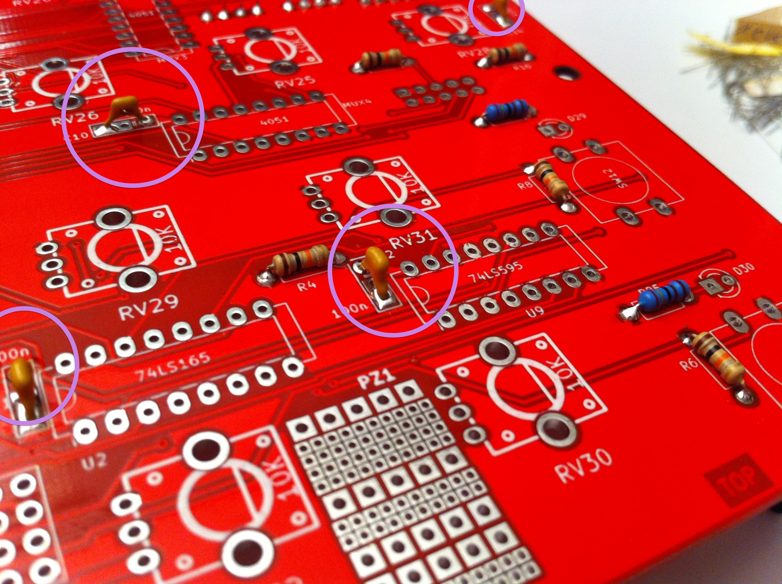
Step 7 : decoupling capacitors
C1, C2, … C13.
These are unpolarized and marked as 104 (= 100 nF). They are used as « energy reserve » for the ICs next to them. It’s easier to solder them if you push them on their side.

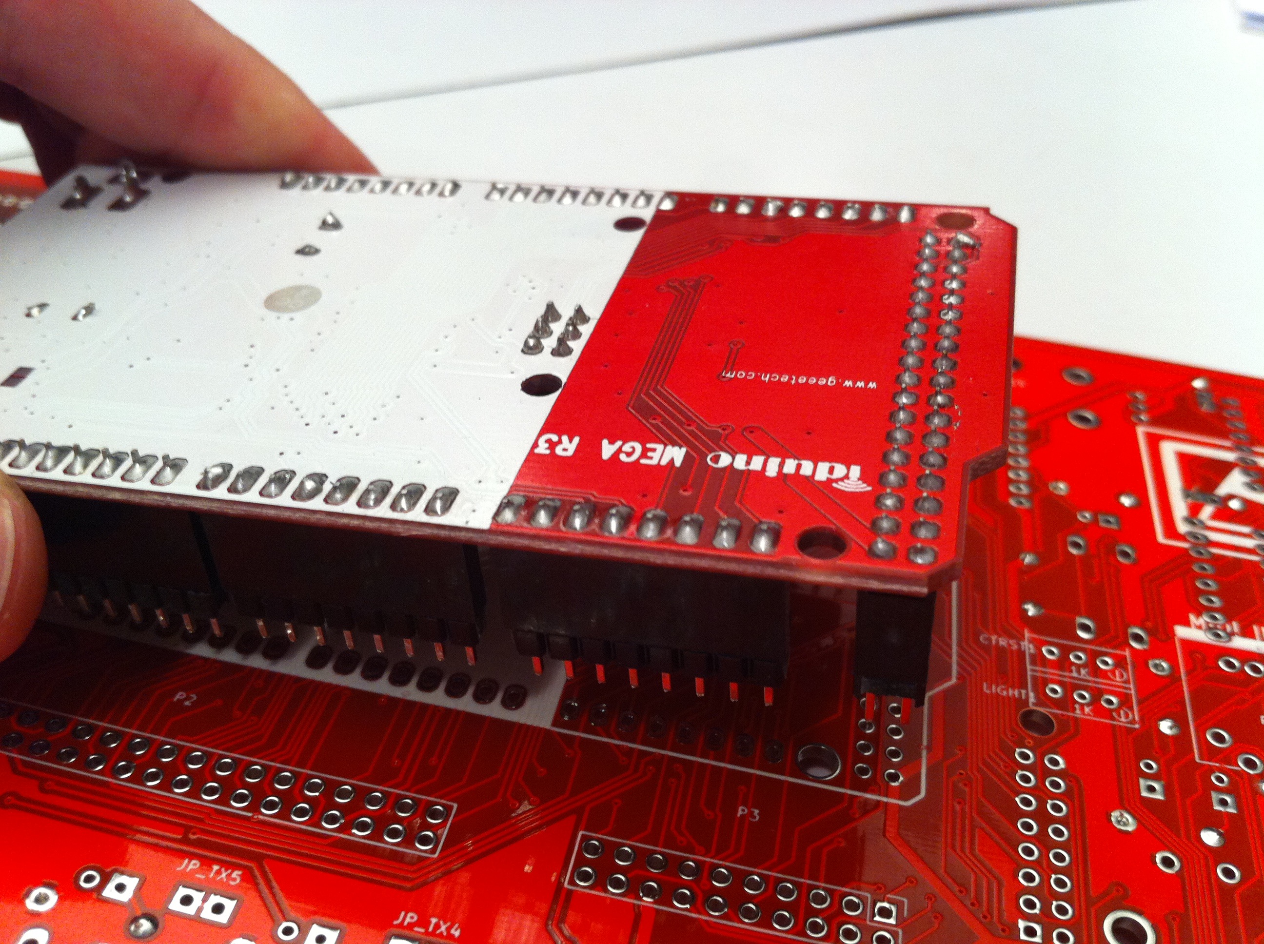
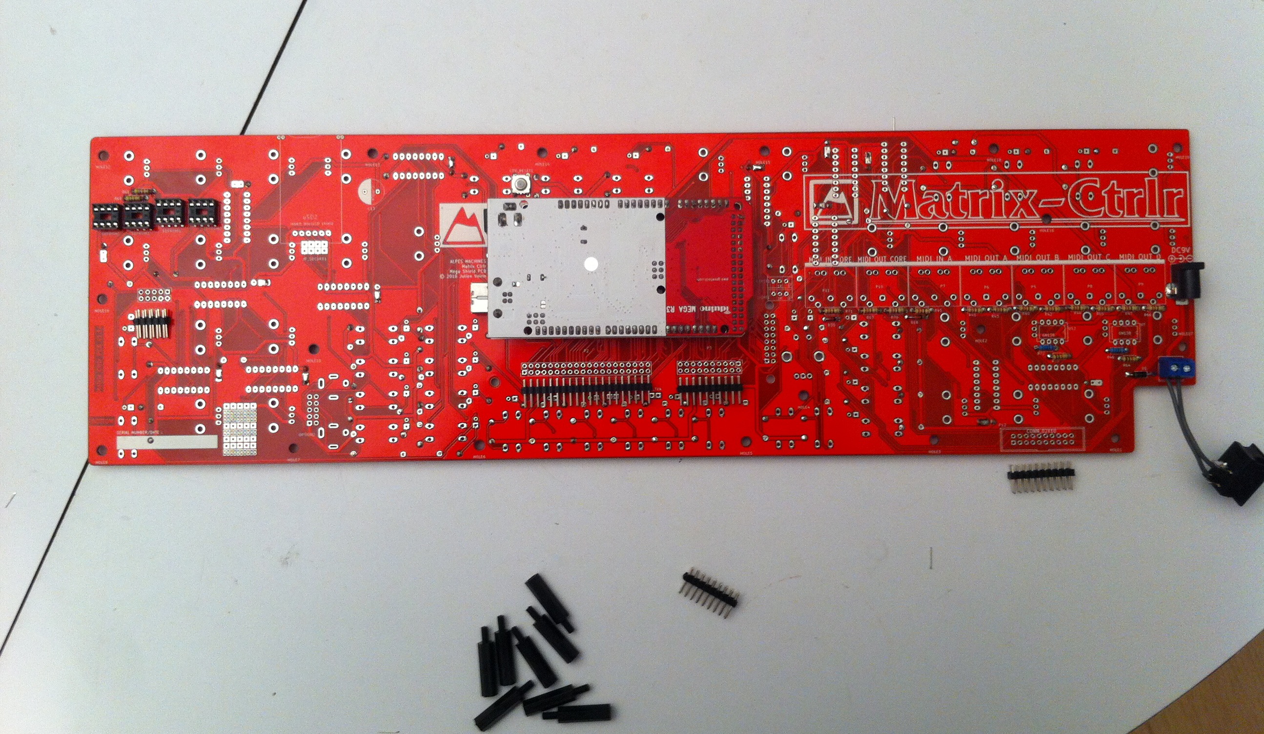
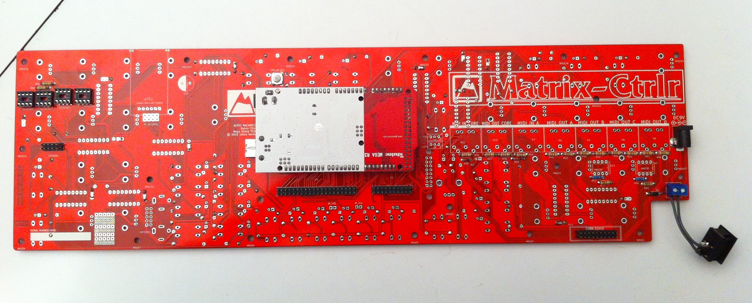
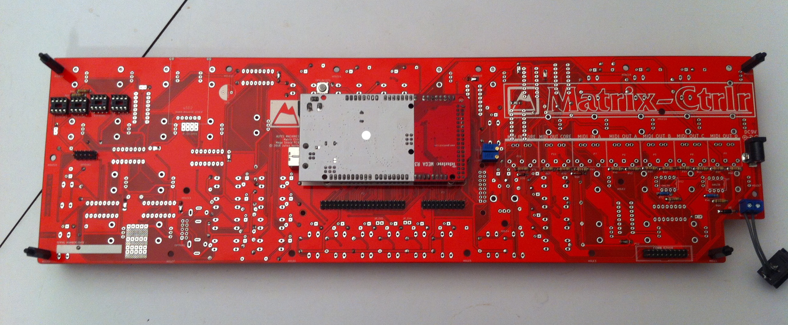
Step 8 : pin headers connectors on back
2X40 AND 1X40 PIN-HEADER
Cut the appropriate length pinheader to create :
- Arduino : 1×6 + 1×8 +1×8 + 1×8 + 1×8 + 1×8 , 2×18.
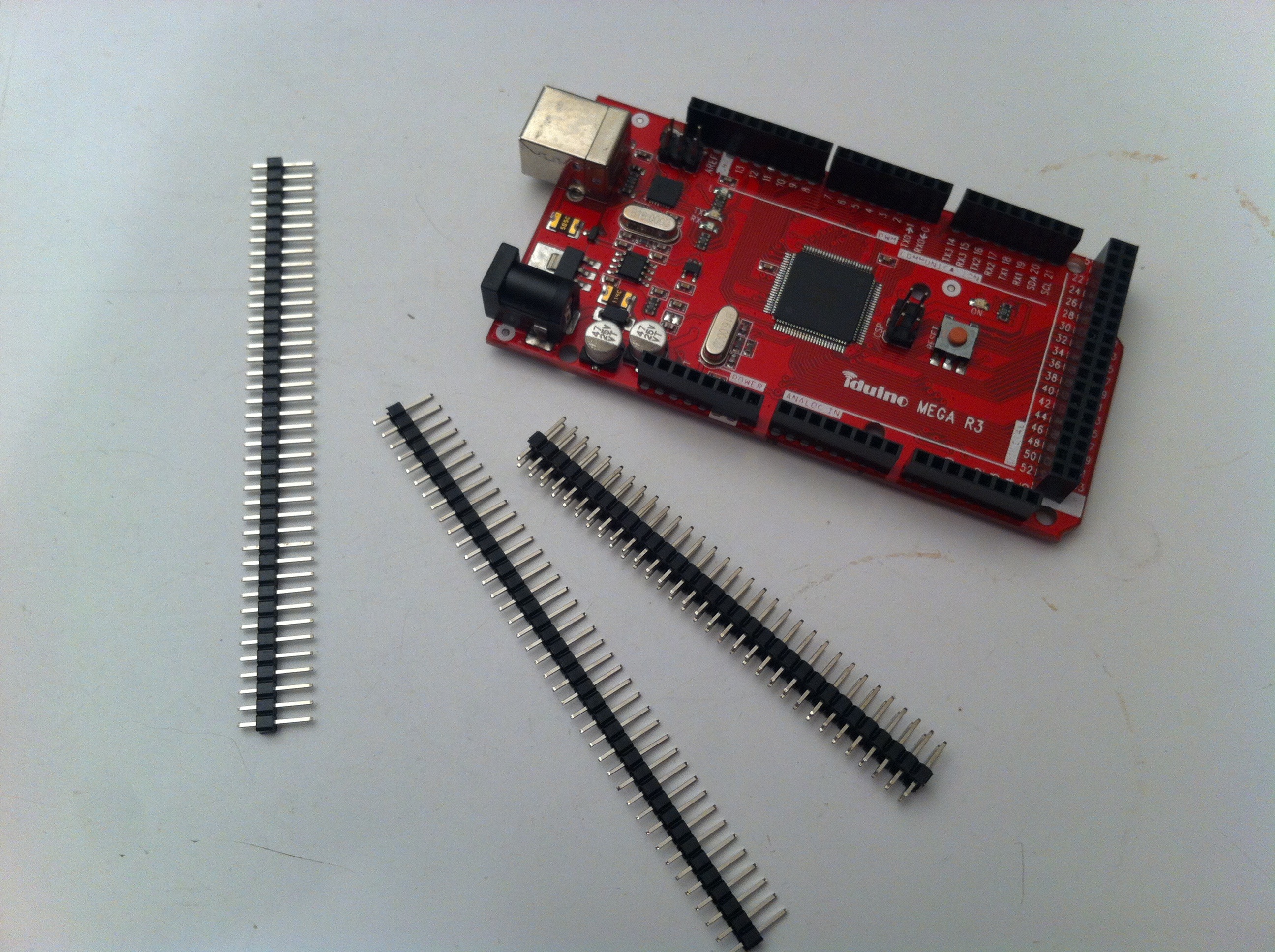

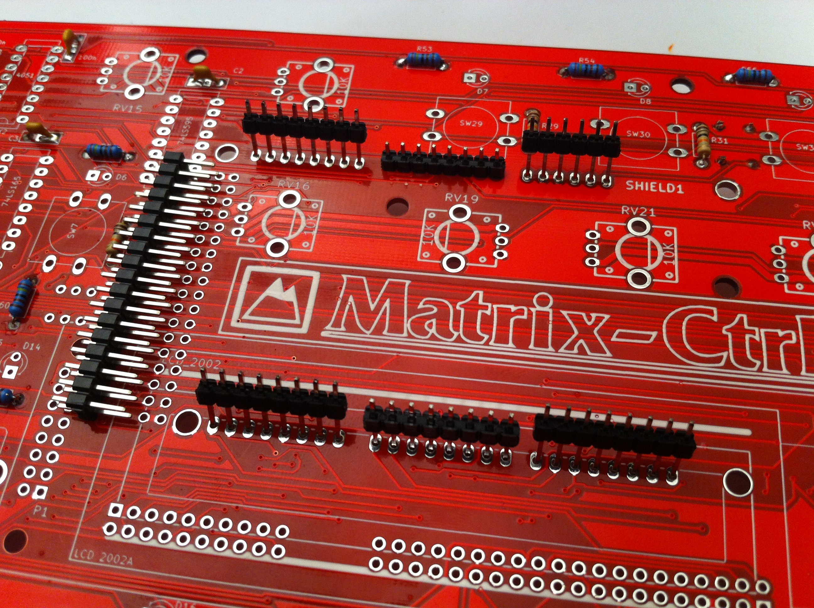
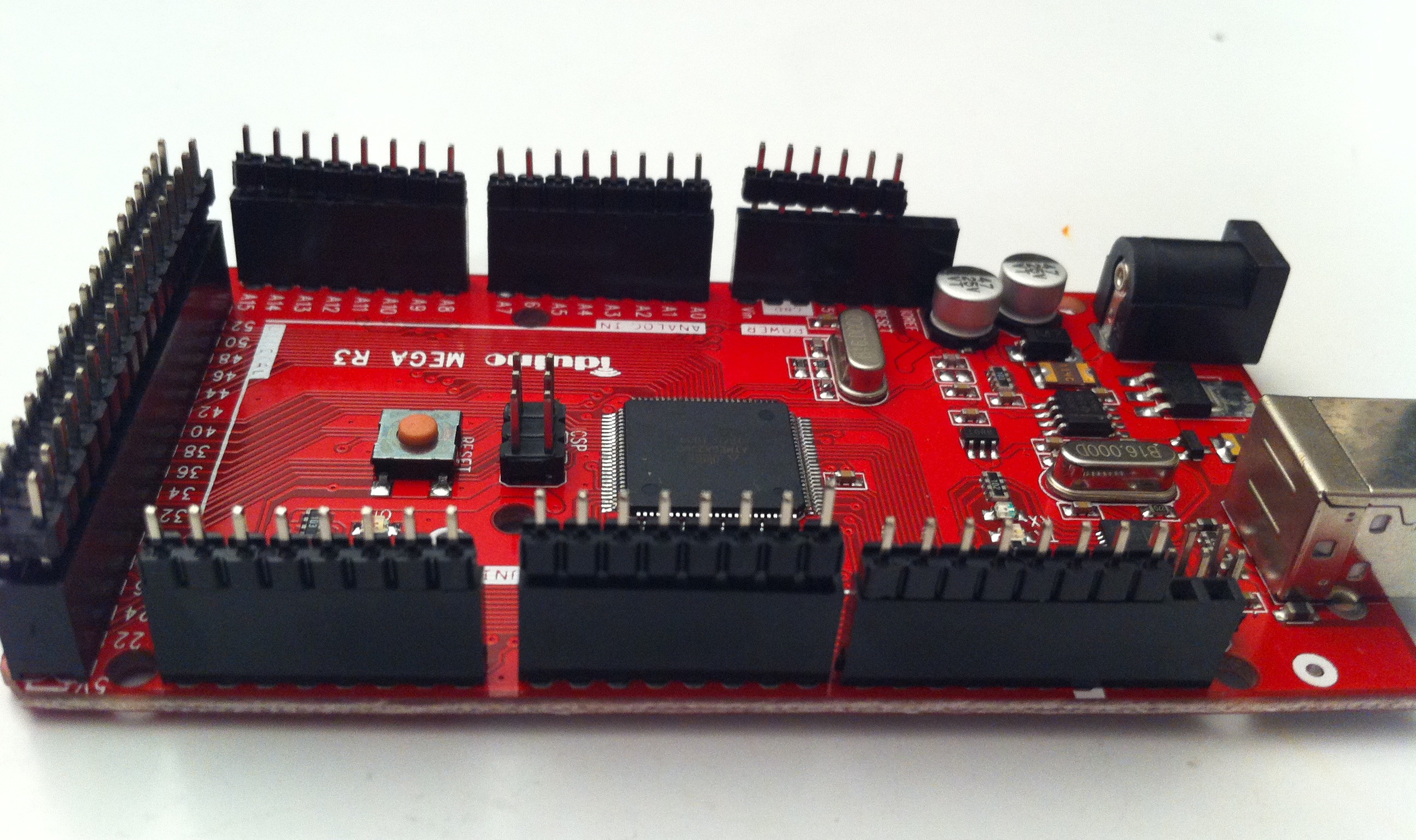
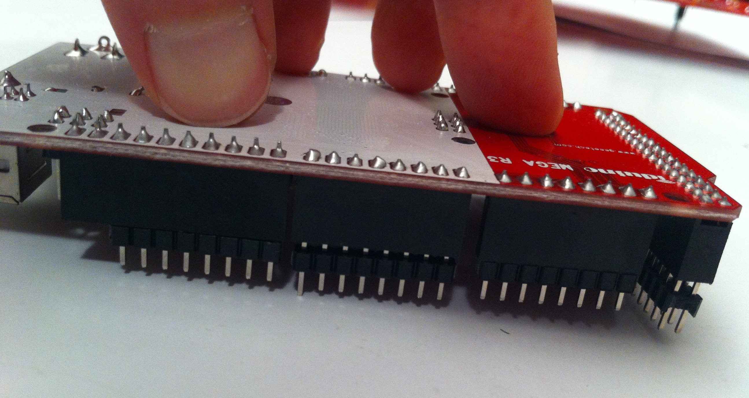
Place them in the female connectors on the arduino board, then insert the whole assembly into on the back of the PCB. Push with your hand as best as you can and solder them in from the top.
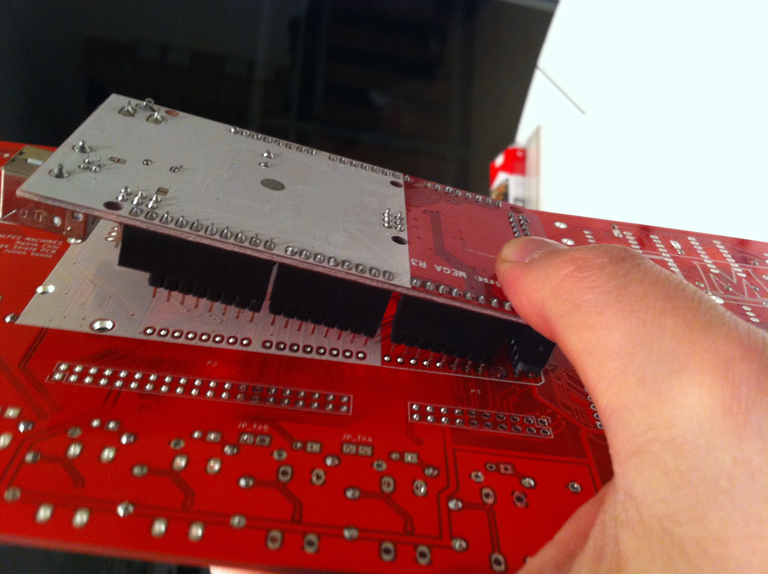
- PCB :
P2 = 2X10 (REQUIRED !)
P3 = 2X20 (REQUIRED !)
OPTION1 = 2X5
OPTION2 = 2X5
P12 : 2X10 or special IDC box header
Solder these the best you can at a right angle to the PCB.
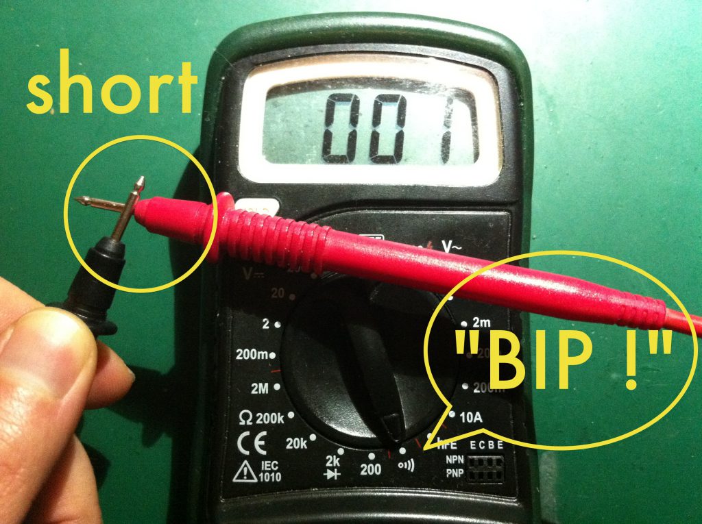
It’s time to check the power supply using your multimeter.
First, check that the power rails and ground rail are not shorted using the « bip » section of your multimeter. Pin 4 and 8 of the DIP-8 footprint are the perfect location for that.
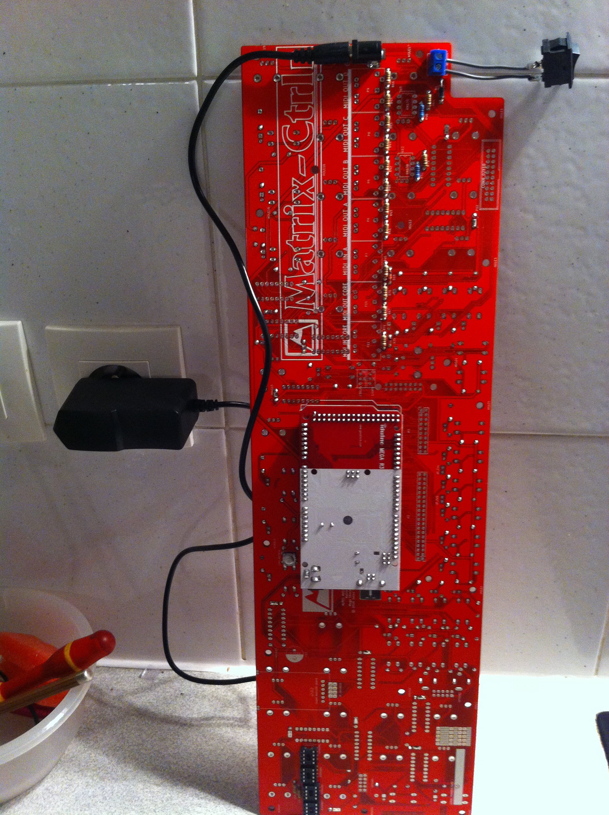
Connect the 100-250VAC to 9VDC power adaptor to the DC barrel and switch it on.
A green LED (the power LED) should light up on the MCU board.
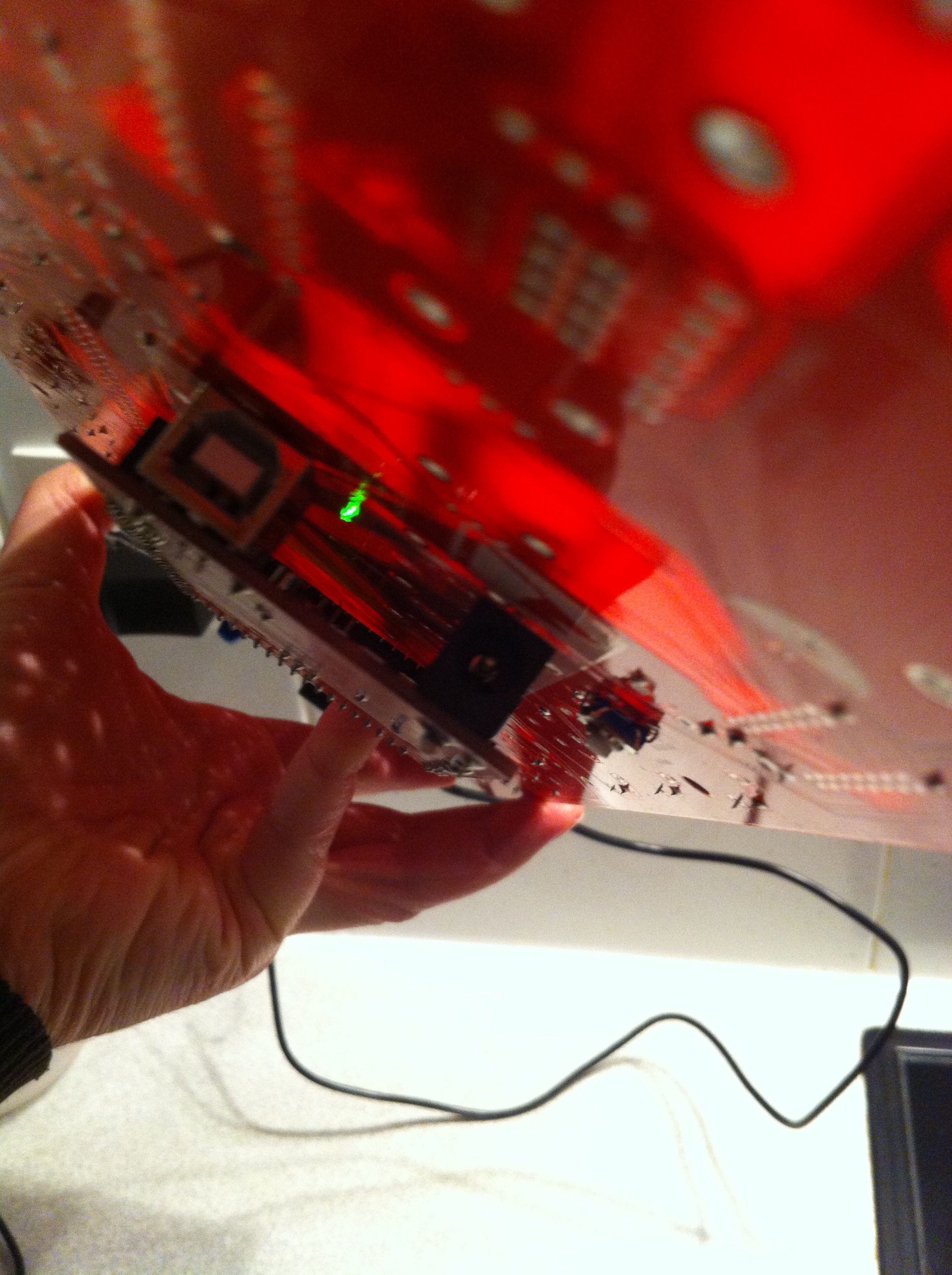
You should notice that the arduino has powered up via a green LED lighting up on the arduino mega board.
If NOT, switch the power OFF !
Measure +5VDC between pin 4 and 8 of EEPROM3. Or between pins 1 & 3 of the potentiometer footprints.
Hint : You can use test points TP1, TP2 & TP3 to check PSU voltage and +5V
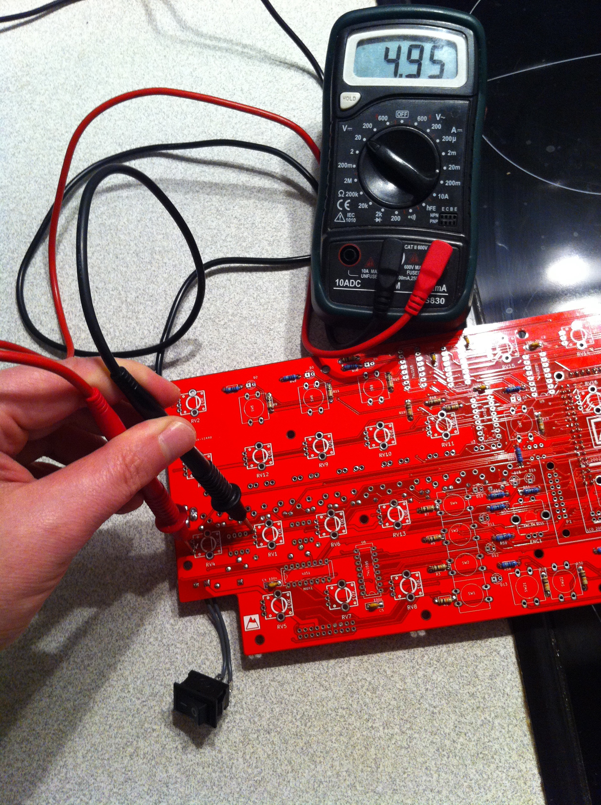
If your measurement isn’t +5V DC +/- 10% , there is a short circuit somewhere.
If it is, your circuit is well powered. Remove the power adaptor from the DC socket and mount the active components. Place the 24LC512 in their sockets.
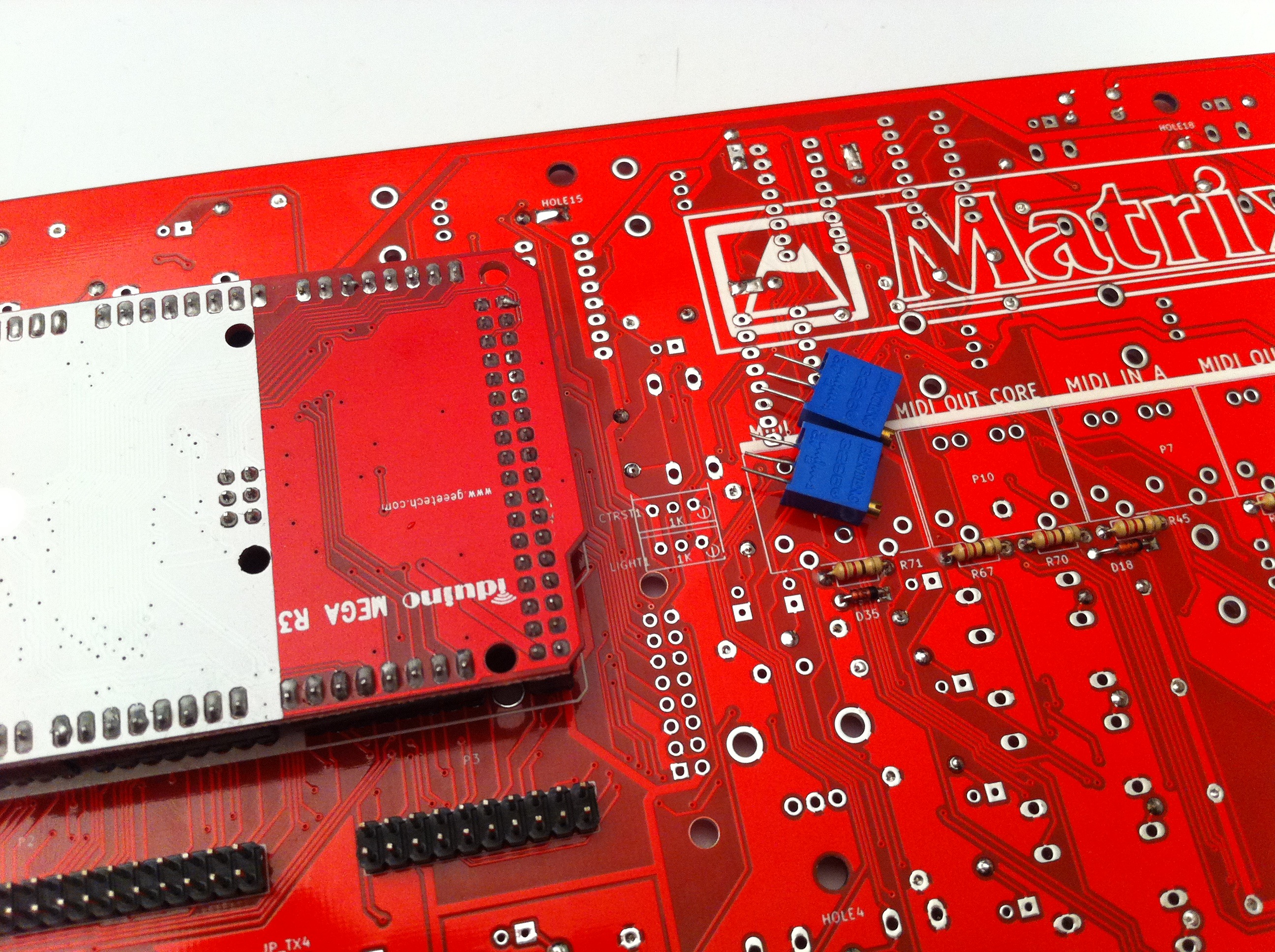
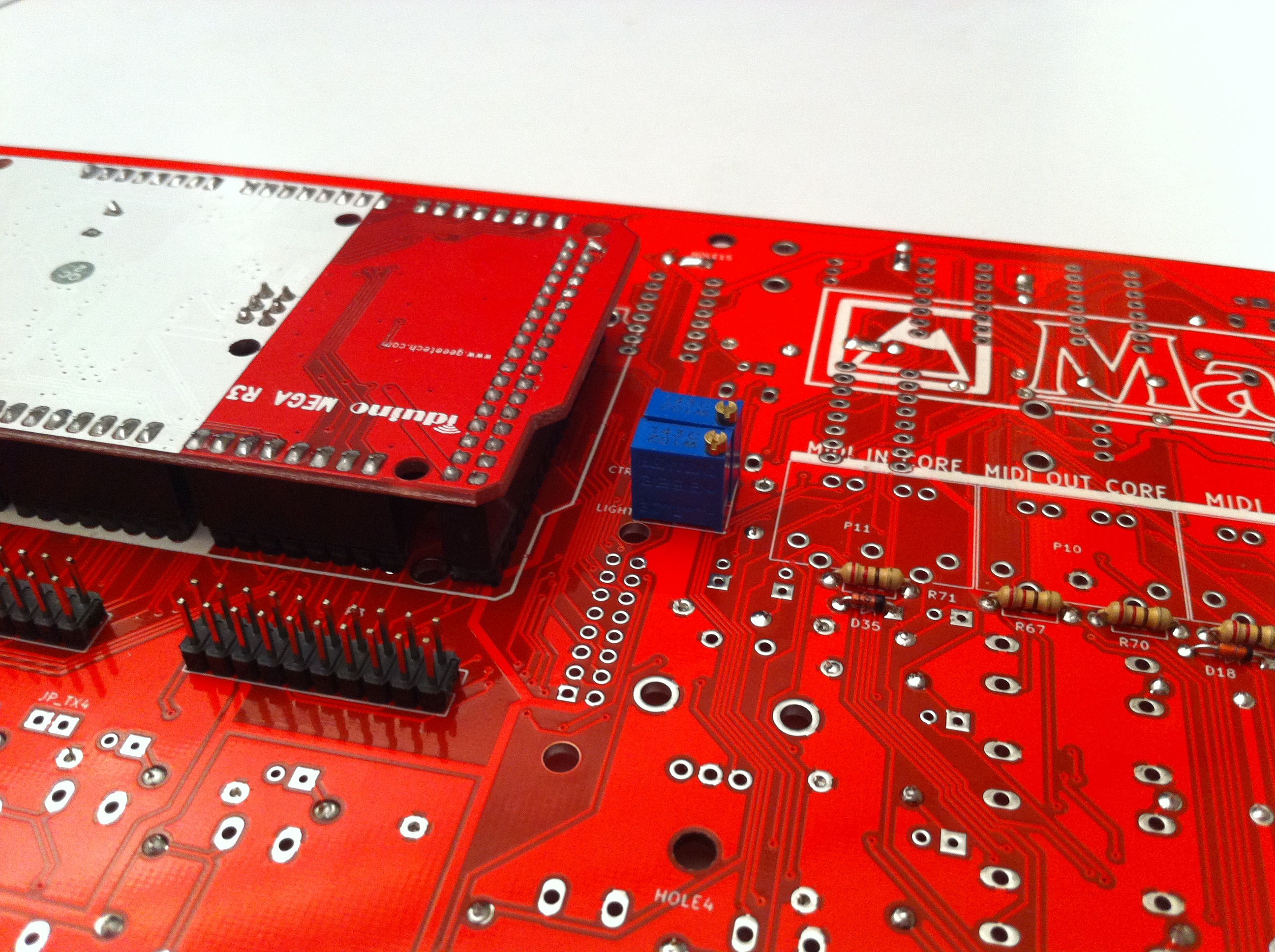
Step 9 : 1K trimmers
CTRST1 & LIGHT1
Place these on the back of the PCB and extend their leads to them from falling out. It’s a good idea to solder only one lead and then push with your finger while ironing to attach it tight to the PCB, then solder the other leads.
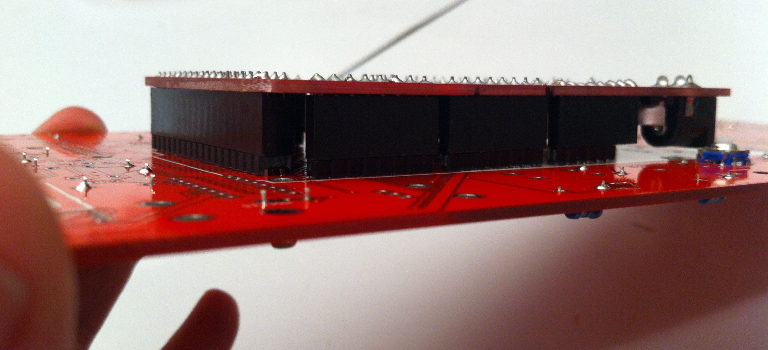
Step 10 : MIDI Sockets
P11 P10 P7 P6 P5 P8 P9
Flip the PCB over to see the bottom.
Place DIN5 sockets the best you can and solder only one of their leads from the top. Then, using your iron and your hand, push each socket, one by one, as flat as possible to the PCB. Notice their alignment. If needed, correct by reheating the soldered lead.
Next, flip the PCB over and solder the remaining leads from the other side. Go slowly: these need more solder because of the hole size. Make sure to check their alignment as you go.
If you power the Matrix Ctrlr on now you should get random midi messages at the MIDI OUT.
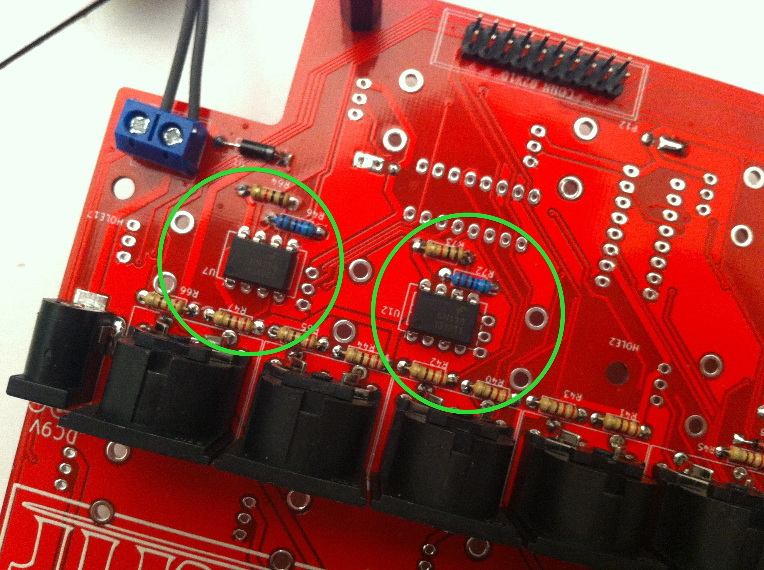
Step 11 : optocouplers 6N138
U7, U12.
Solder these to the bottom of the PCB. Notice their notch orientation !
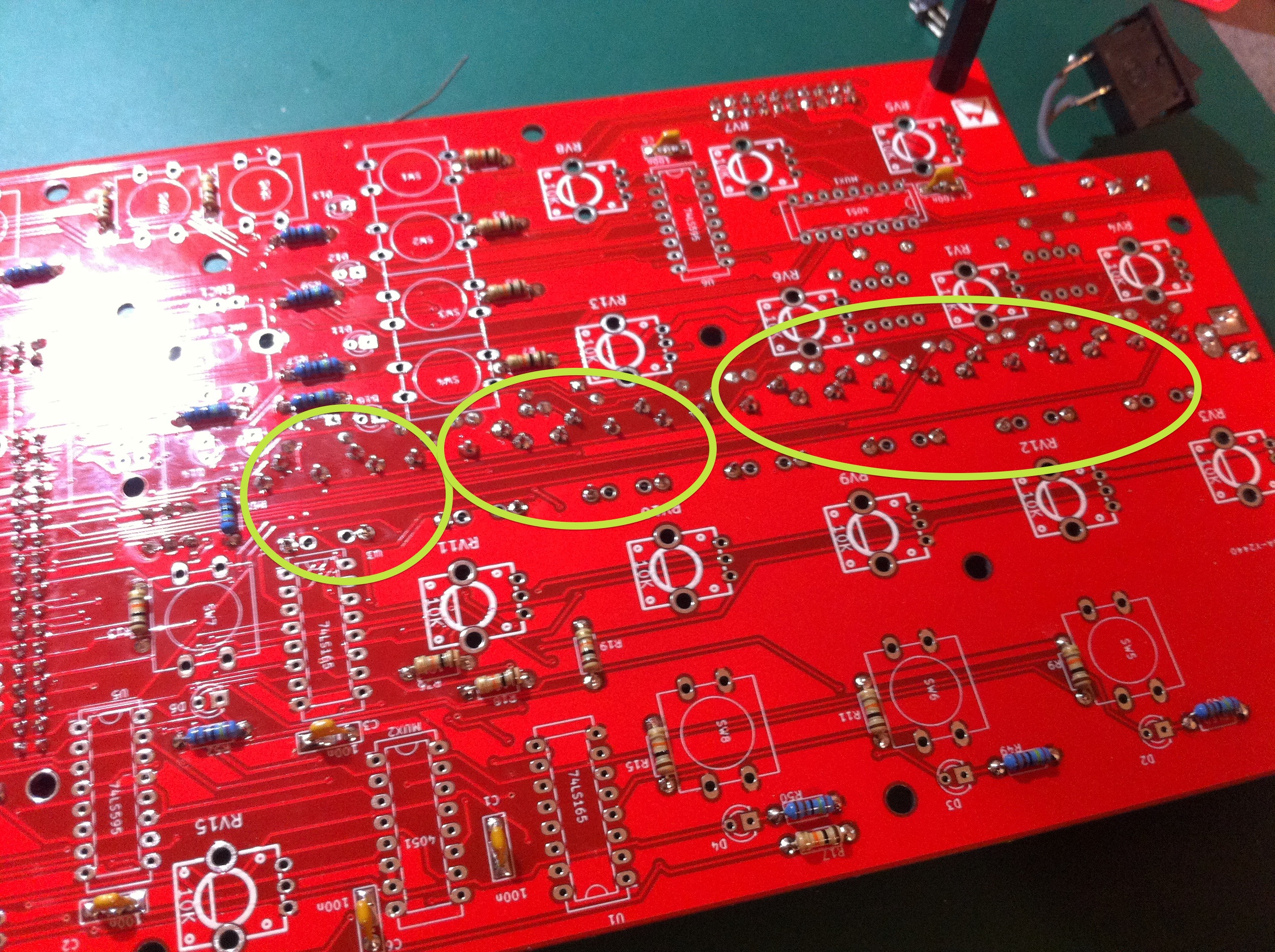
Step 12 : ICs
ANALOG MULTIPLEXERS CD4051 : MUX1 MUX2 MUX3 MUX4
SERIAL IN SHIFT REGISTERS 74HC595 : U6 U8 U9 U5
SERIAL OUT SHIFT REGISTERS 74HC165 : U1 U2 U3 U4
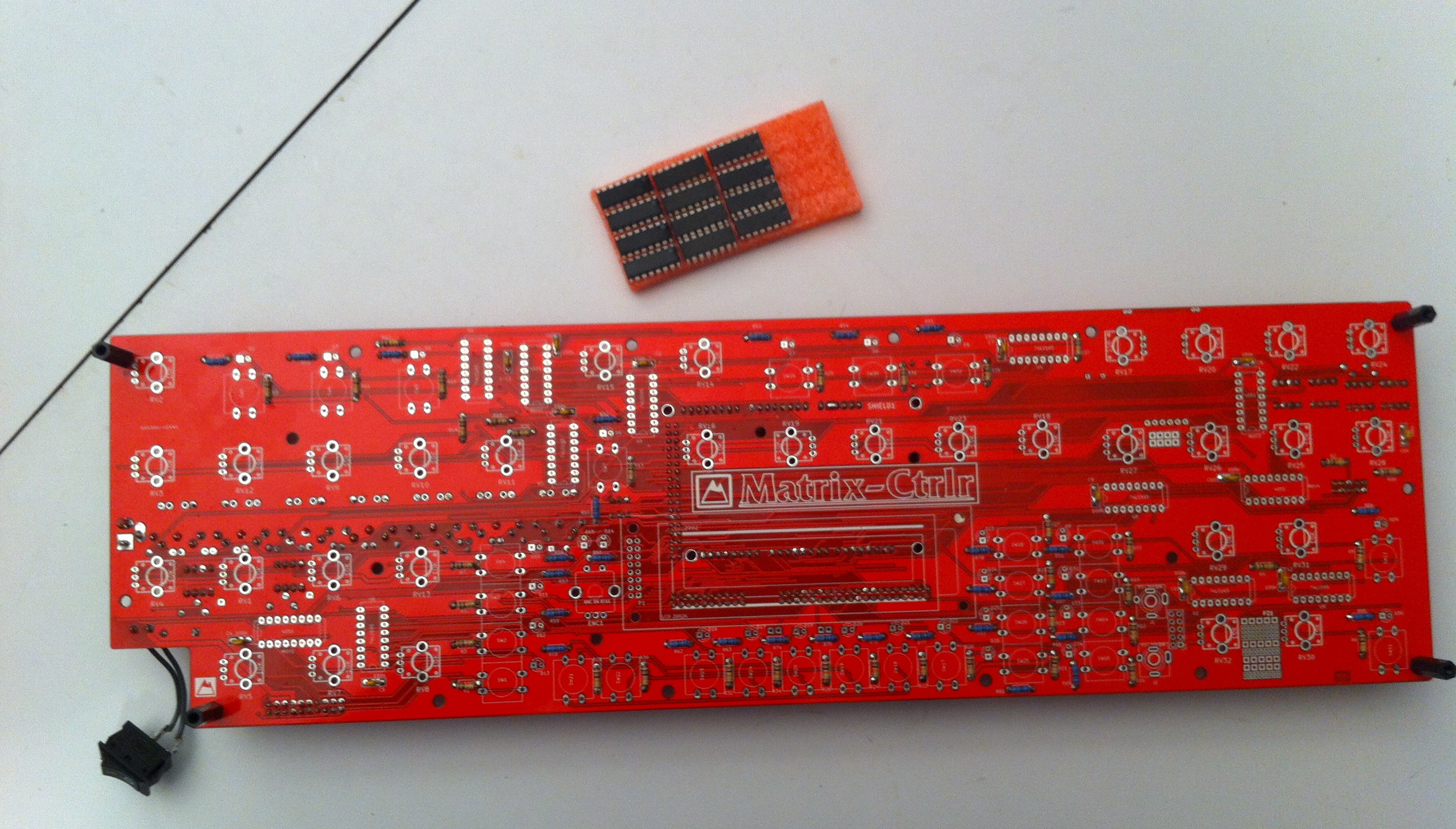
Pay attention to their orientation : triple check you placed them correctly before soldering ! It’s a good idea to use DIP16 sockets.
Make sure the alignment of the notches on the ICs match their alignment in this picture :
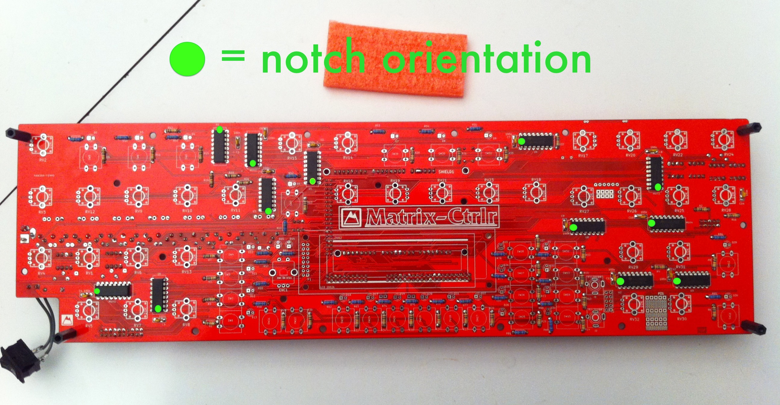
Does everything look good? OK. Check once again. Then solder.
Hint : use DIP-16 sockets if your are not an experienced DIYer as desoldering could damage PCB traces. You can easily find them on eBay or your local electronic retailer at cheap price.
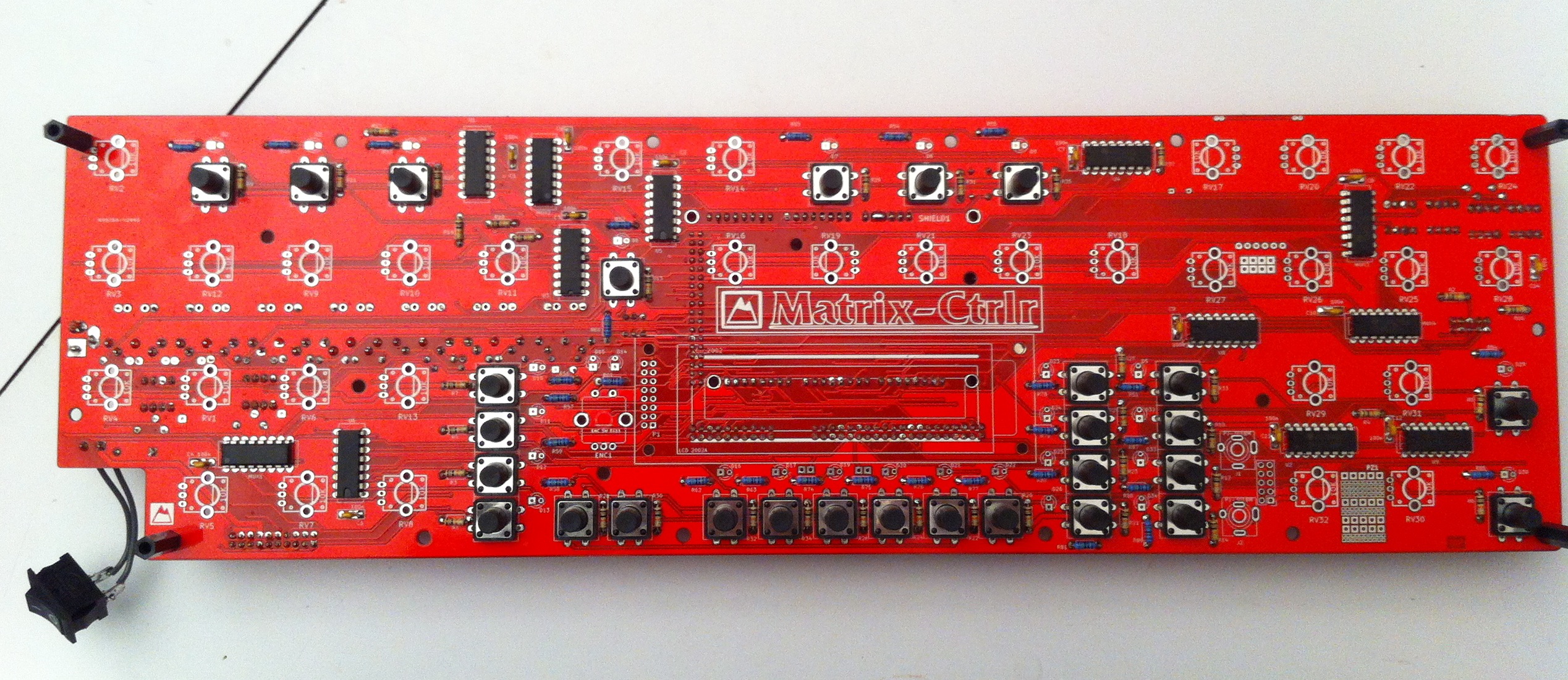
Step 13 : Switches
SW1, SW2, … SW31
You can just insert these without soldering at this time. You will need to adjust them while assembling the sandwich later.

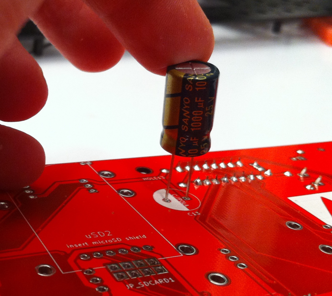
Step 14 : Polarised capacitor
C/POLA (1000u/25V). max height 20mm ! (OPTIONAL)
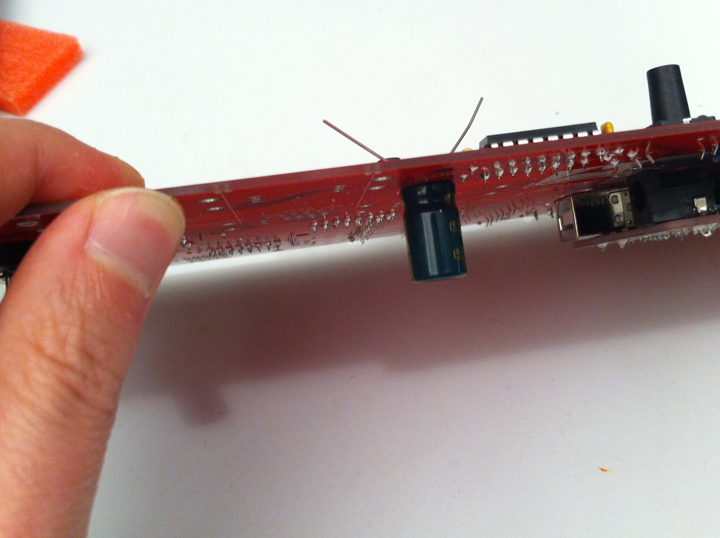
The kit is furnished with a 1000uF/25V or 10V polarized capacitor. It can be a different value, only the size matters (yes Madam). Its height must be less than 20mm. Its role is to be a big stock of energy.
Important: The white area on the footprint signifies the negative (-) lead. Don’t insert the positive lead into this side of the footprint! Stick it to the PCB the best you can (height matters).
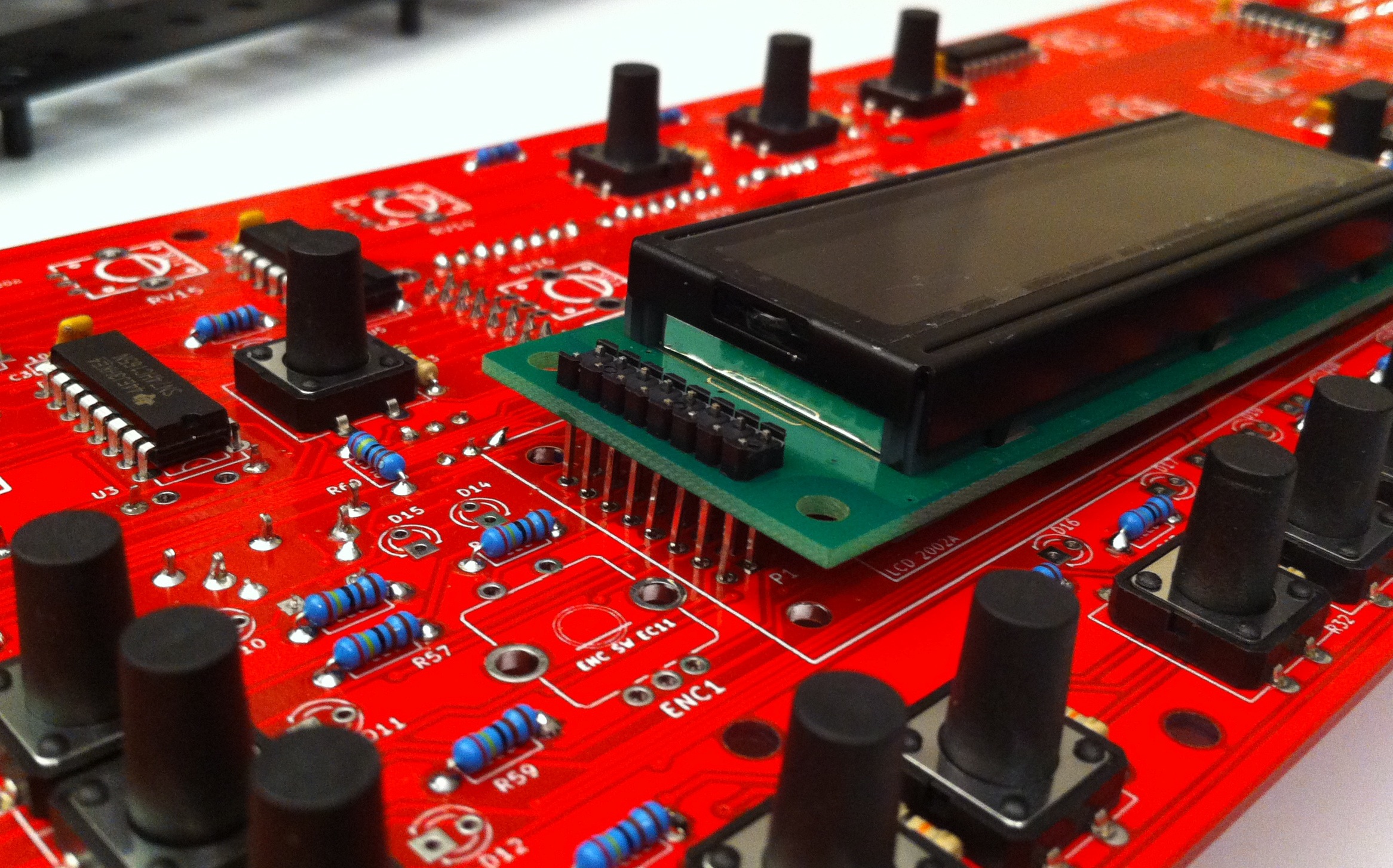
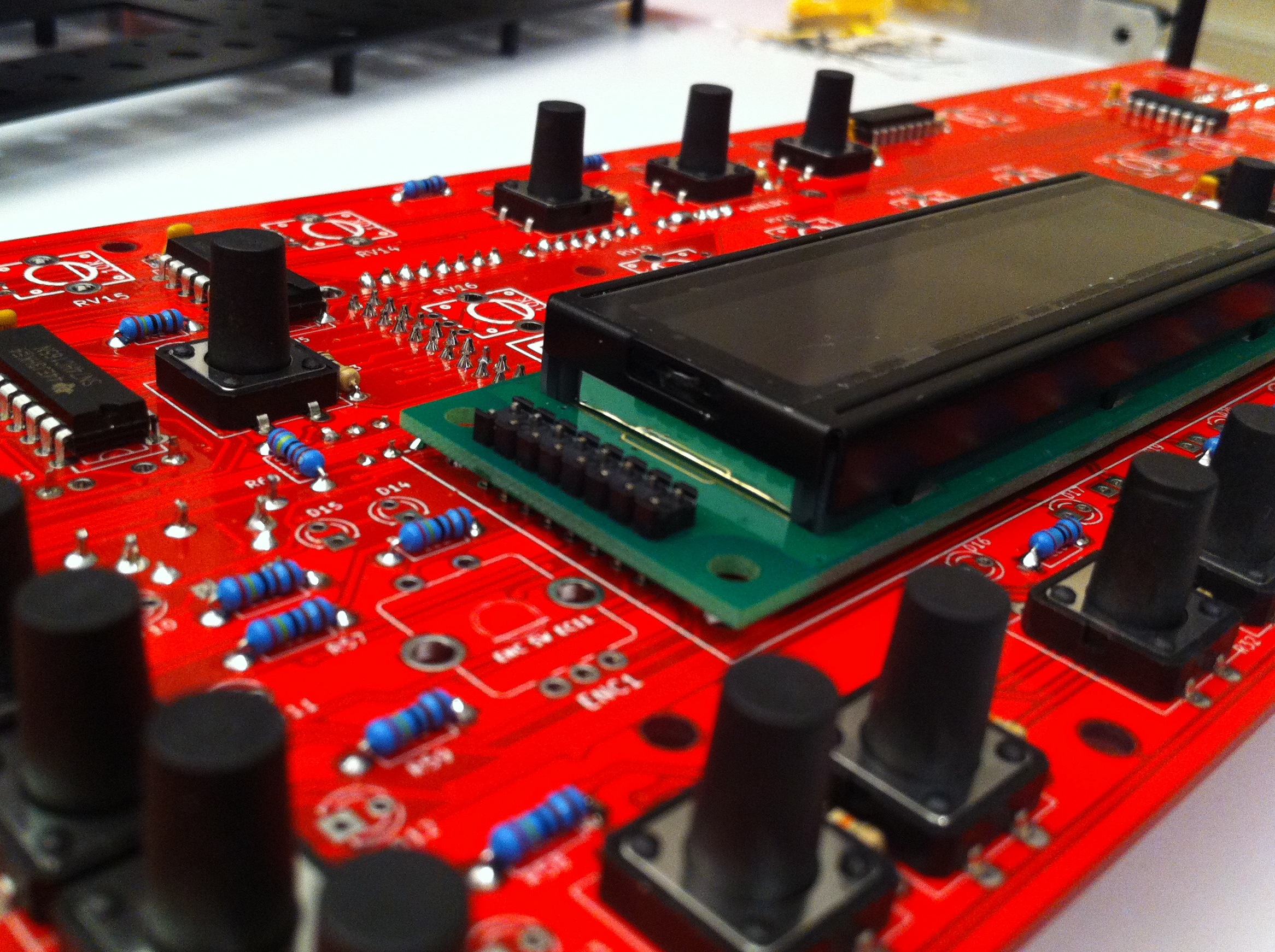
Step 15 : LCD
Retrieve the DIL2x8 pin-header you put aside for the LCD and solder it to the LCD board as in the image below.
This needs to be perfectly aligned at a right angle for the mechanical assembly of the Ctrlr.
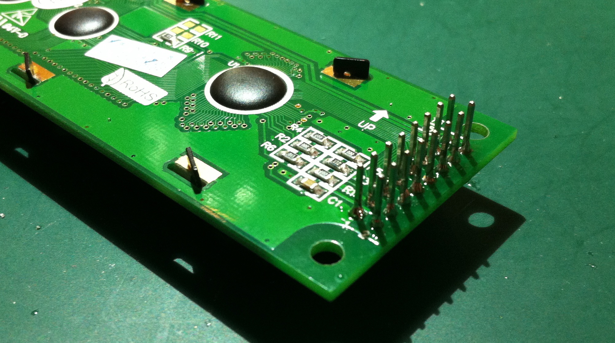
DO NOT SOLDER IT TO THE PCB YET !
This concludes the first part of the build process.
Next, go to Building Matrix Ctrlr : assembly.