Troubleshoots
![]()
![]()
Resulting from customers building experience on several Matrix Ctrlr, here are the common possible problems you could encounter and their symptoms/solutions. It’s a good idea to use sockets for ICs as this allows you to swap a component by another one (there are usually several same units on the Kit for a given value) and decide whether or not it’s defective.
It’s also a good idea to check your soldering first as it is the main cause of trouble.
All LEDs have been tested before shipping (to sort them regarding their dimming characteristics). ICs have always been protected in antistatic containers. Other components have been stocked in antistatic drawers or boxes (no plastic bags).
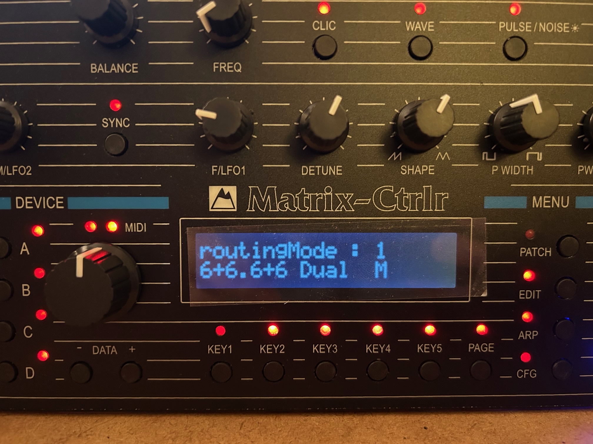
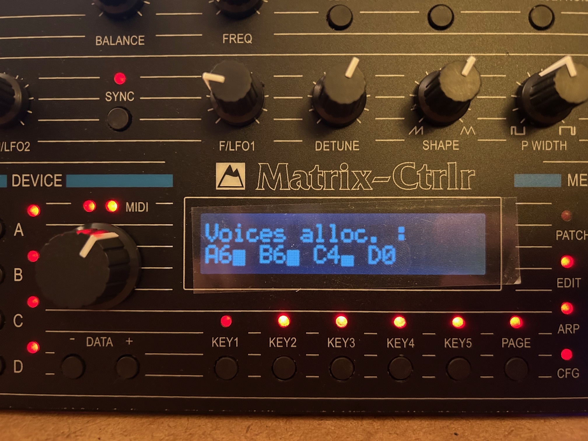
It appears that some 74HC165s from the first batch are randomly defective (certainly a factory bad batch) after several hours of use. Here is a screen shot :
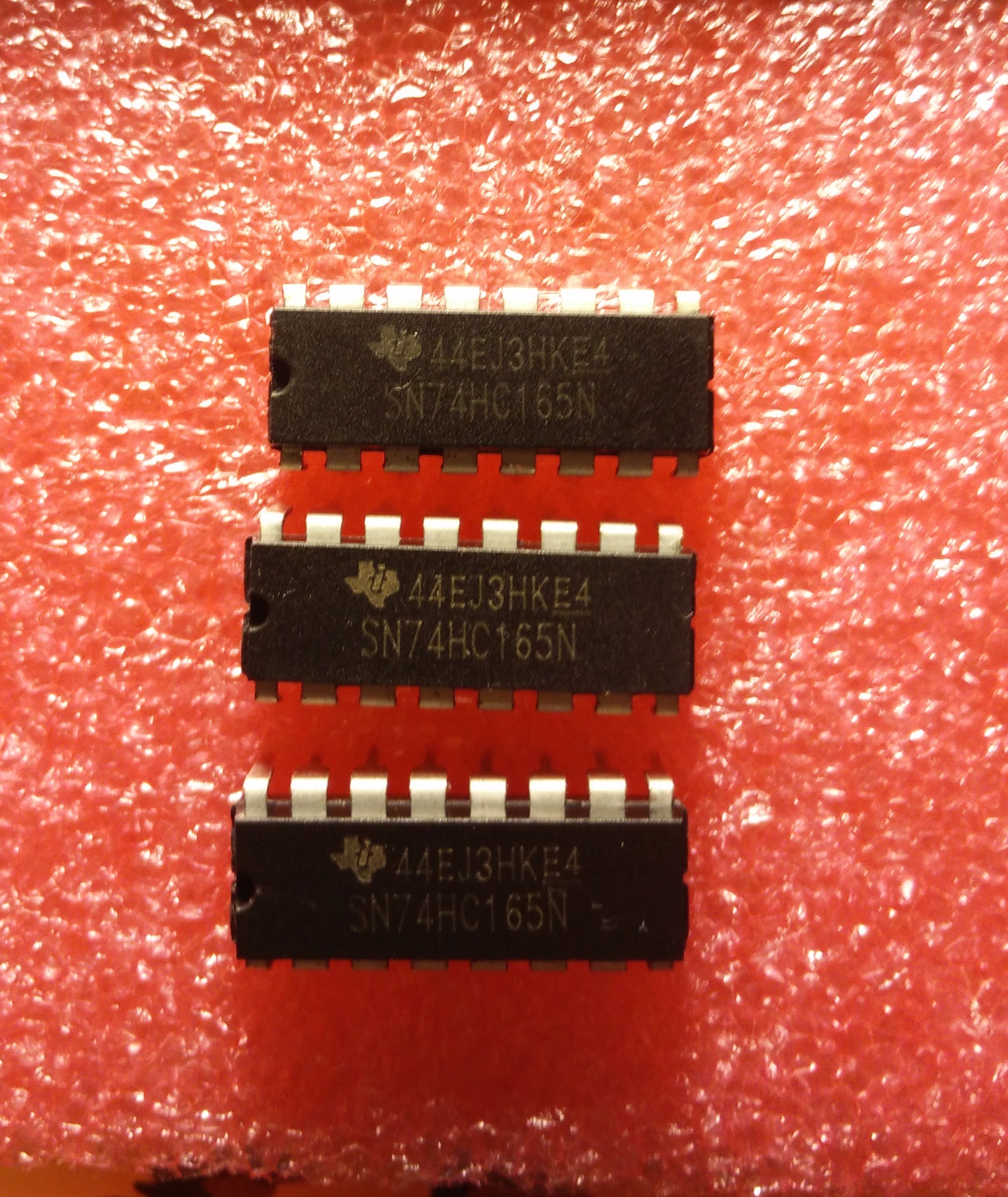
It’s strongly advised to use sockets for those shift registers in order to swap them for new ones when needed, in the future.
Random messages on screen corresponding to potentiometers parameters controls :
- one or several pots are defective (stress while snapping caps) : replace for a brand new pot
- bad or missing soldering on pot terminals or CD4051 : solder better !
- wrong orientation of CD4051 : remove and replace (swap with another one available)
LED not working :
- wrong orientation of LED : desolder and solder it right back
- attached RLed badly soldered (cold solder joint) : better solder
- check soldering on 74HC595 pins
Switches not working :
- check soldering of switches and 74HC165 sockets.
- 74HC165 defective : replace it.
MIDI IN not working :
- check 6N138 orientation
- check D18, D35 orientation
- replace 6N138 (swap two units)
LCD not working :
- check soldering of P1 (critical step) on the LCD and on the Mainboard !
- check orientation of LIGHT1 and CTRST1 trimmers regarding their footprint. If you invert them they still work but clockwise turn becomes counter clockwise turn.
- check PSU and voltages on Ctrlr : +9V DC on input and +5V DC on board.
I had fried the voltage regulator of an iDuino Mega using another old power supply brick wall. The LCD was completely white (too much contrast and voltage on board was 12V). The Ctrlr had an erratic behavior. But the iDuino was still working by USB supply after that ! From this experience, i can tell that the Matrix Ctrlr is rather resistant to voltage stress as nothing was defective after iDuino board replacement.
The PSU furnished by Alpes Machines is new and good quality. The one of your Guitar pedals could be hazardous …