Alpes Machines is very sorry and presents his apologies :
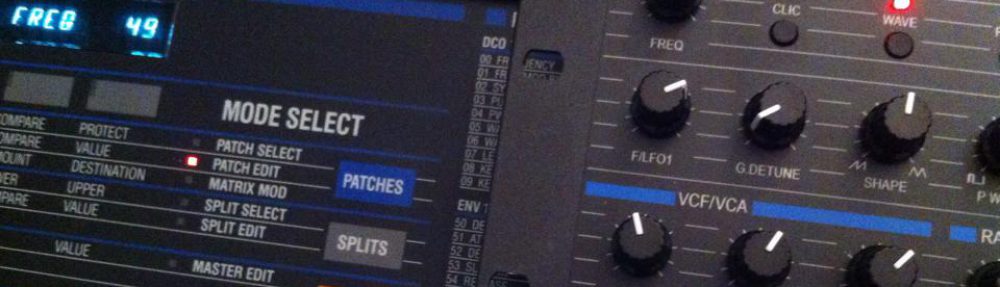
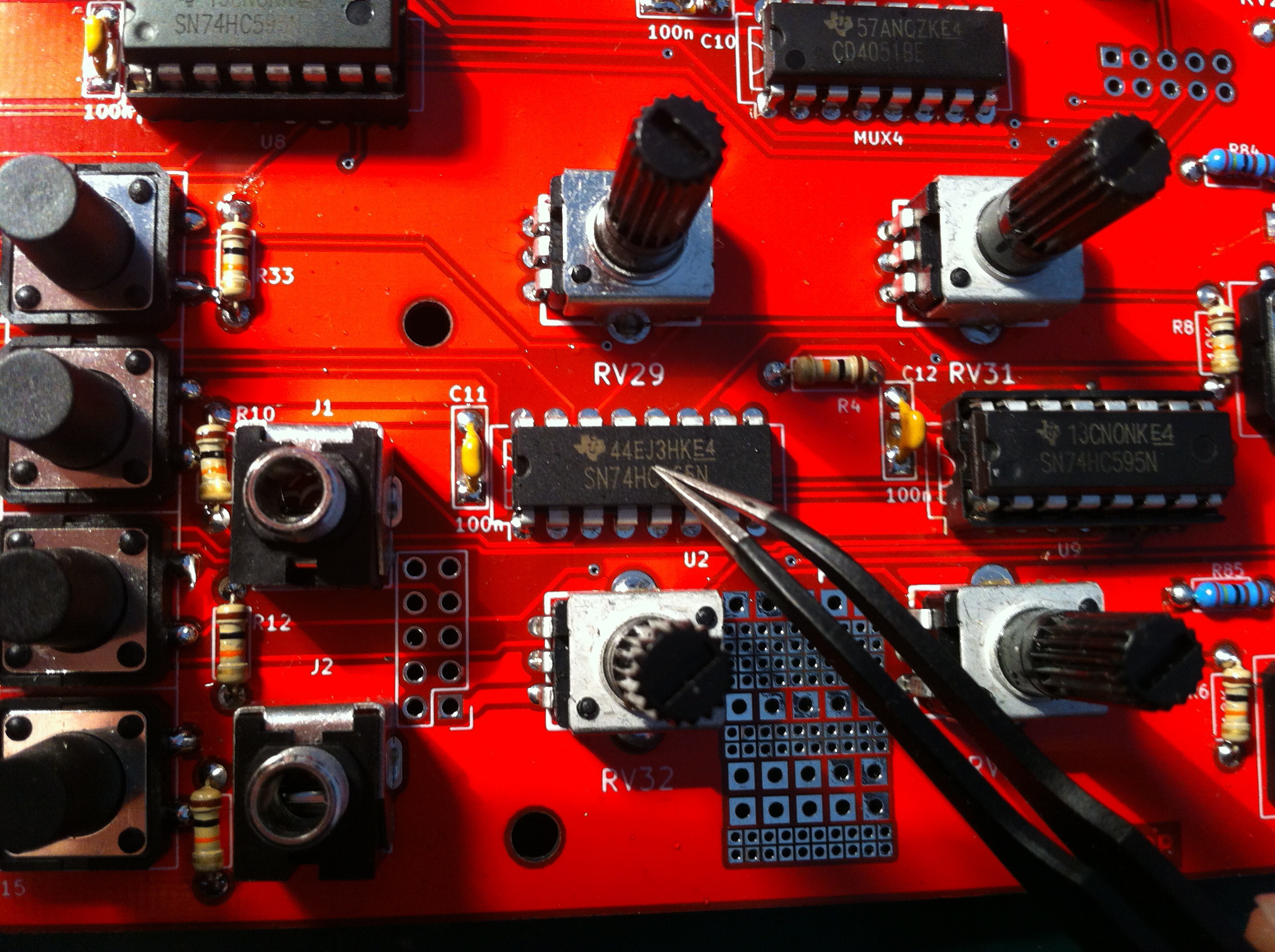
It has been discovered that some 74HC165s from the first batch are randomly defective (certainly a factory bad batch : 44EJ3HKE4) after several hours of use. The sourcing has been changed since. Here is a screen shot :
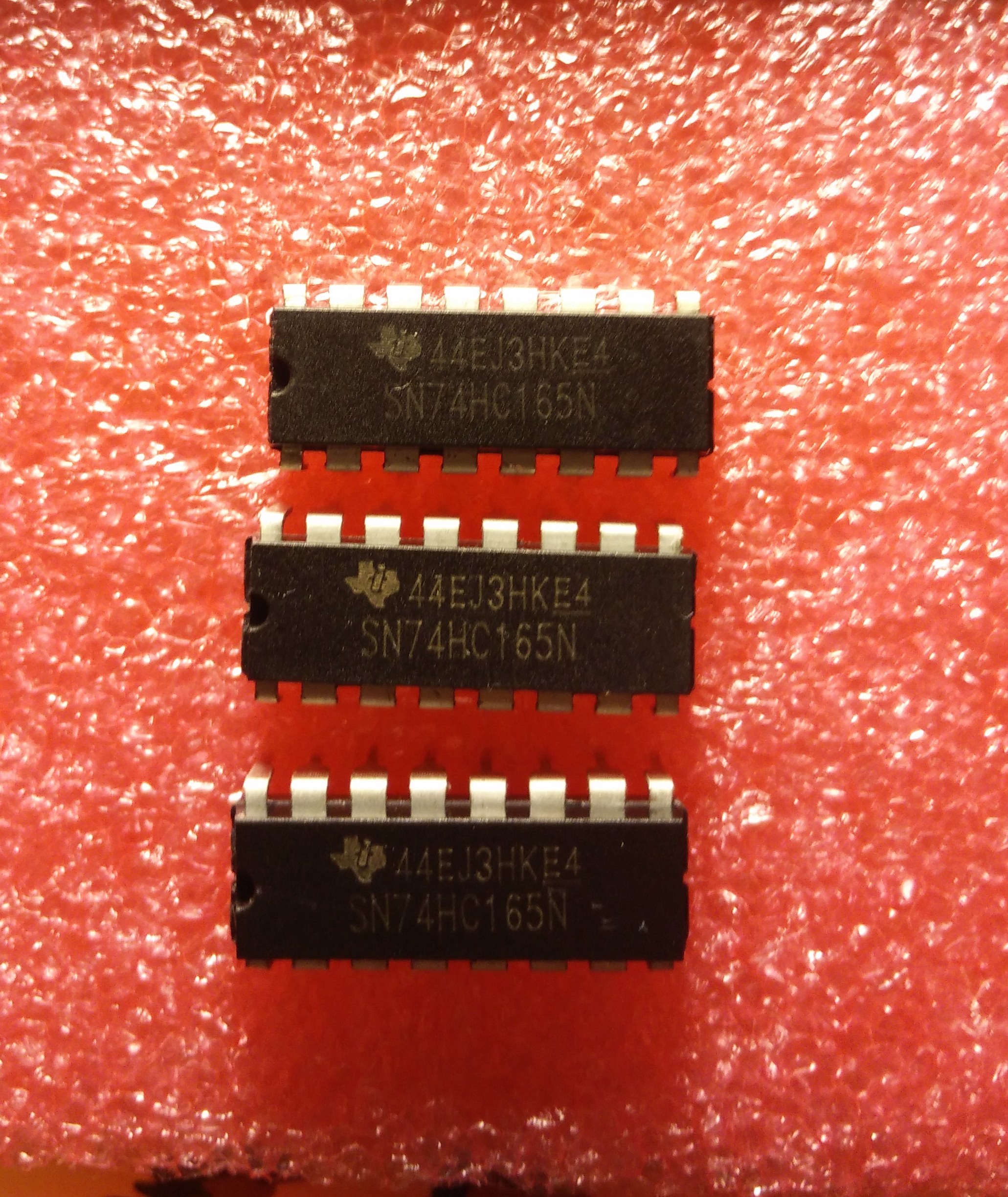
It’s strongly advised to use DIP16 sockets for those shift registers in order to swap them for new ones when needed, in the future, or to change them now for brand new ones.
Mouser’s part : 595-CD74HC165E
They are easily available worldwide in electronic components stores or on the internet (#74HC165 ) for a few bucks (or you can ask us some samples).
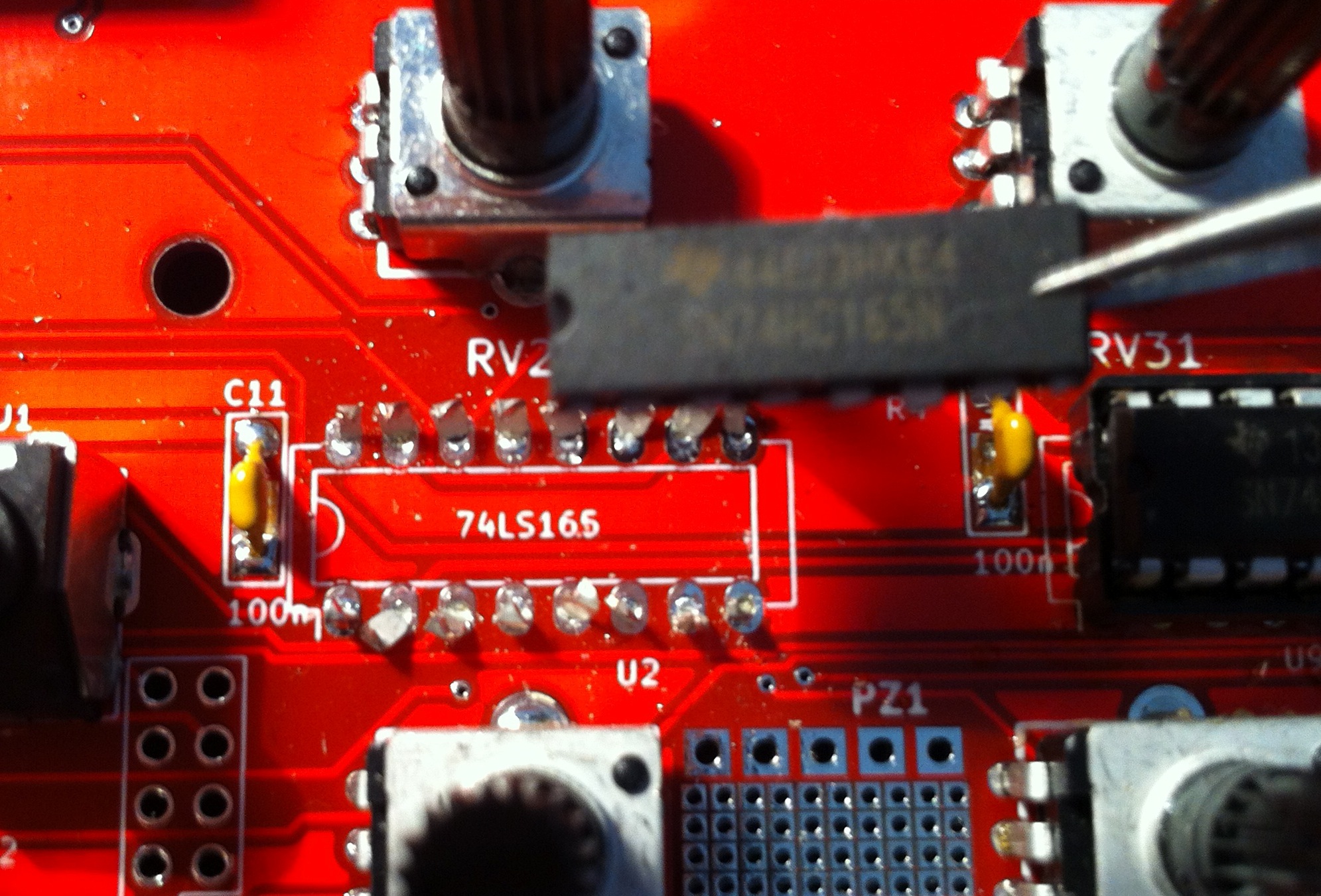
The serial out shift registers 74HC165 are used to “decode” the buttons press. So if you discover that the buttons are not working correctly, it is certainly the fault of ‘165s.
./..
But now that you’ve discovered that the shift registers are faulty, what to do ? Well, you need to remove them. We will sacrifice them and replace them for a DIP16 socket + brand new 74HC165. Ideally you would remove them with a desoldering station.
If you don’t have a desoldering station, there is an efficient process :
- Remove as much as possible the solder
- Cut the legs to remove the body of the shift register
- Remove the leg of each hole
- Clean the holes
You will need the following tools (especially desoldering wick/braid) :
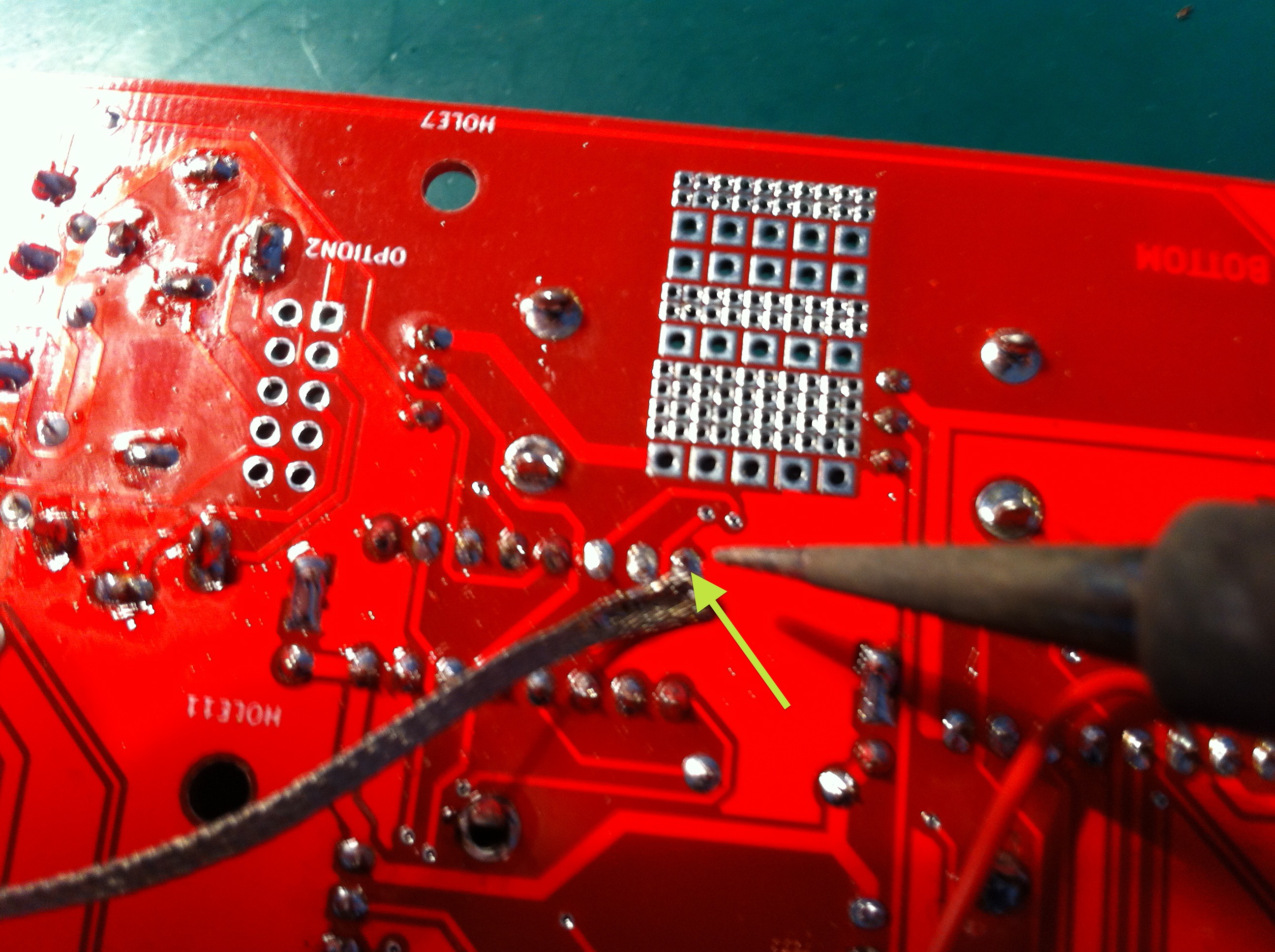
Use the braid to remove as much as possible the solder from the pads, softly pushing with your iron (set on 320°C), first from center and, then, from the sides to the center of the component, on the BOTTOM side of the PCB.
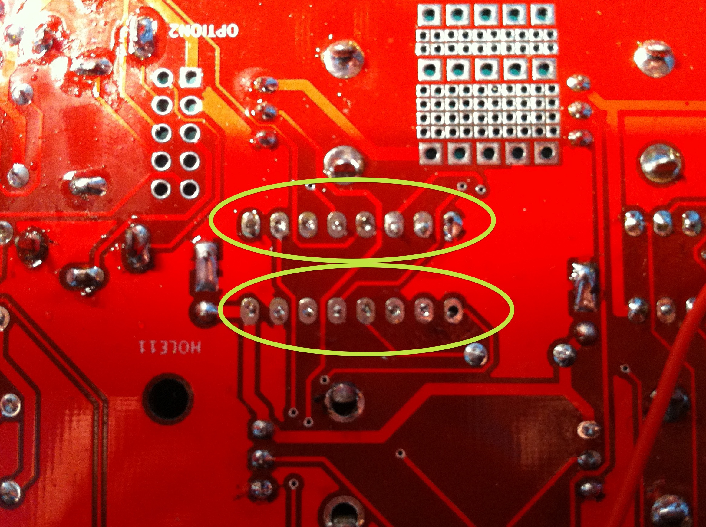
Then you cut the leg by pushing on sides of each adjacent legs to force the tweezer between the legs. Be as possible at the vertical, and start on leg 1 (the slimmest).
Then, while heating the pad, you remove the resting leg by pulling it with a tweezer.
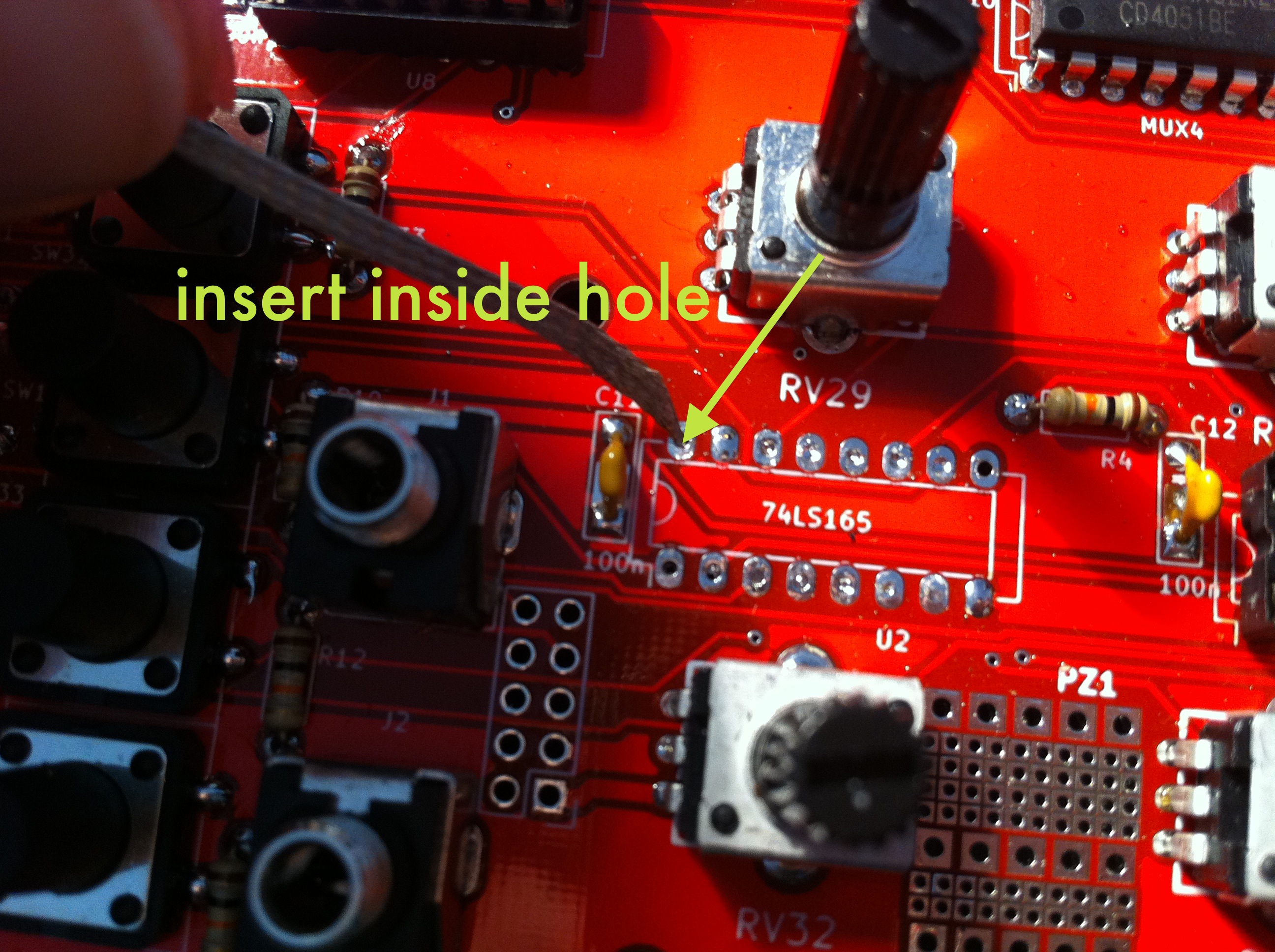
Now just clean the holes using the bread, ideally by not ironing the center, but just around the hole as the rest of solder could melt and close the hole. Don’t apply too much pressure as the heat would deform the pad. You can cut the braid at 45° to insert the end of the wick inside the hole, or use a resistor leg as a wick at the very end :
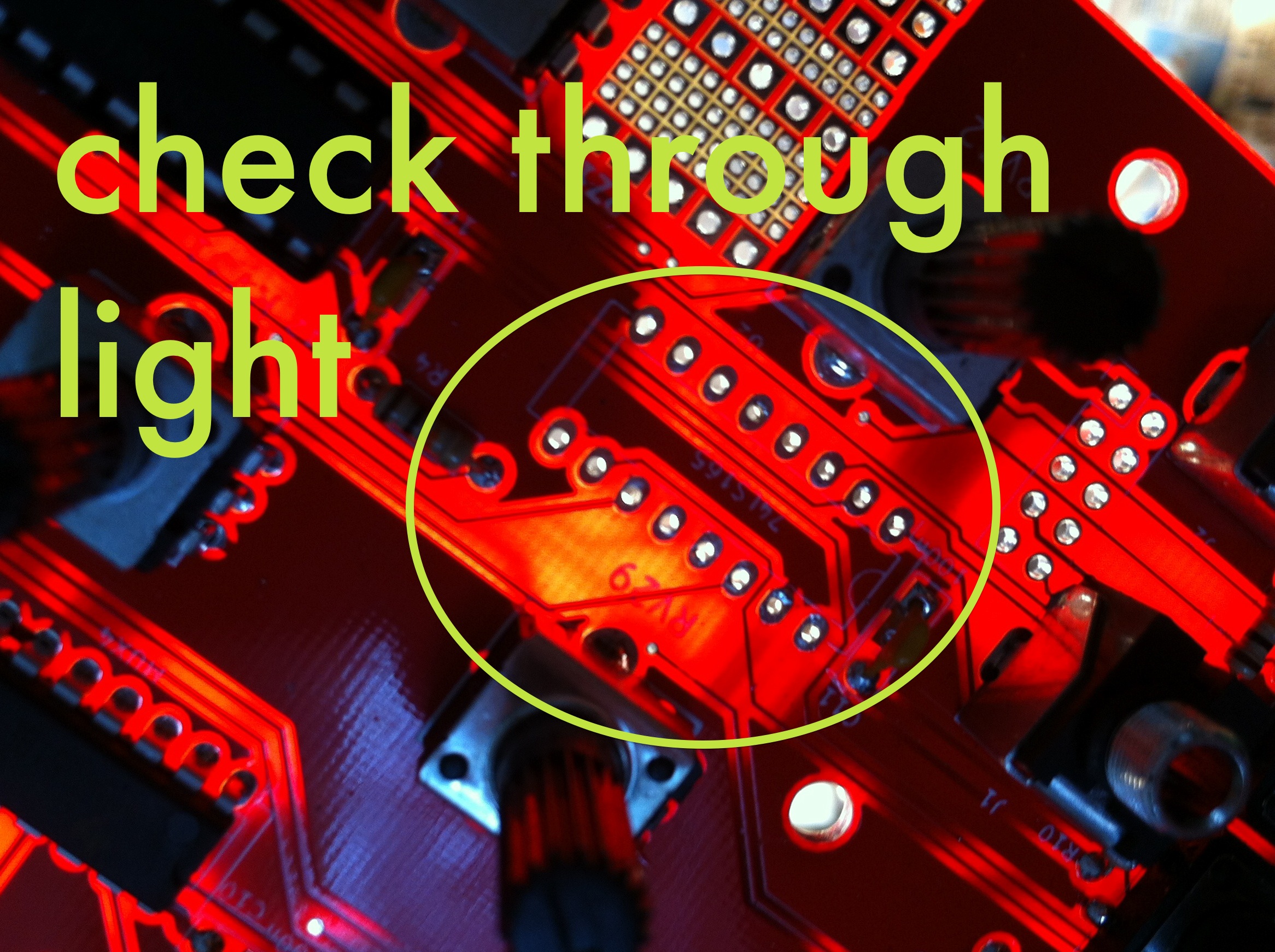
Check in the light that each hole is circular and properly cleaned. Then solder a DIP16 socket, insert the new shift register and it’s done.